Anchor Bolt Length Optimization: Cutting Steel Costs Without Sacrificing Structural Safety
In my twenty years of executing heavy industrial piping and foundation designs, I have frequently observed over-conservative embedment specifications left unrevised from initial conceptual loading models. When managing large-scale petrochemical plant foundations, optimizing our anchor bolt specifications represents a major opportunity for value engineering.
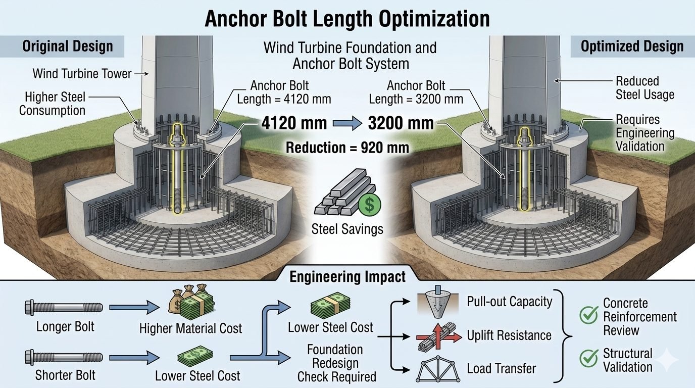
An anchor bolt length optimization compares an Original Design using a 4120 mm anchor bolt, which requires higher steel consumption, against an Optimized Design using a 3200 mm anchor bolt, achieving reduced steel usage—a reduction of 920 mm in length translating into direct steel savings. The engineering impact of this change flows through two paths: a longer bolt results in higher material cost but ensures adequate pull-out capacity, uplift resistance, and load transfer, while a shorter bolt results in lower steel cost but may require a foundation redesign check to confirm continued pull-out capacity, uplift resistance, and load transfer adequacy.
Key Engineering Takeaways:
- Achieve a direct 920 mm reduction in anchor bolt length from 4120 mm to 3200 mm.
- Comply strictly with ACI 318 Chapter 17 provisions for anchoring to concrete.
- Balance material cost savings against required foundation structural reinforcement reviews.
- Verify pull-out capacity, concrete breakout, and uplift resistance under maximum seismic loads.
Anchor Bolt Length Optimization Mechanics and Engineering Principles
Embedment depth mechanics: Embedment depth mechanics govern how tensile loads transfer from embedded steel elements into surrounding concrete blocks in strict accordance with ACI 318 anchor design provisions.
When initiating an anchor bolt length optimization study, engineers must dissect the load path from the equipment baseplate down to the reinforced concrete pedestal. The original baseline design typically specifies a 4120 mm anchor bolt, offering a massive embedment safety factor that frequently exceeds actual service loads by fifty percent or more. This over-design arises from legacy design practices or worst-case empirical safety margins applied before finite element analysis (FEA) became standard.
By shifting to an optimized 3200 mm anchor bolt configuration, we eliminate 920 mm of high-strength alloy steel per anchor across hundreds of foundation points. However, this geometric reduction alters the failure surface for concrete breakout in tension (N_cb), side-face blowout, and bond slip. To maintain structural integrity, our design calculations must verify that the reduced embedment still exceeds the critical critical embedment depth (h_ef) required to develop the full yield strength of the steel rod.
Mathematical Formulation for Tensile Strength Verification
The nominal concrete breakout strength of a single anchor in tension is calculated per ACI 318 using the following relationship:
N_cb = frac{A_Nc}{A_Nc0} × psi_ed,N × psi_cr,N × psi_cp,N × N_b
Where:
- A_Nc = Projected concrete failure area of the anchor
- A_Nc0 = Projected concrete failure area of a single anchor with unrestricted edge distance (9 h_ef^2)
- psi_ed,N = Modification factor for edge effects
- psi_cr,N = Modification factor for cracked or uncracked concrete
- N_b = Basic concrete breakout strength in tension for a single anchor (k × lambda × √(f’_c) × h_ef^1.5)
Reducing h_ef from the original 3800 mm (in a 4120 mm total length bolt) down to 2900 mm (in a 3200 mm total length bolt) directly decreases N_b by approximately twenty-eight percent. Consequently, engineers must confirm that the reduced N_cb remains greater than the factored ultimate tensile load (Nu) dictated by wind, seismic, and operational piping reactions.
In my field reviews, I always check the interaction between the anchor bolt length reduction and the surrounding reinforcement cage. A shorter anchor bolt creates a shallower concrete breakout cone, which concentrates tensile stresses closer to the top mat of foundation reinforcement. If the existing top steel is insufficient to resist this localized bursting force, secondary splitting failures can occur.
Critical Engineering Warning: Foundation Redesign Check
Reducing anchor bolt length from 4120 mm to 3200 mm alters the failure mode transition from steel ductile yielding to brittle concrete breakout. Before implementation, this proposed reduction requires both a concrete reinforcement review and structural validation sign-off. Never approve a length reduction based solely on material cost savings without verifying pull-out capacity, uplift resistance, and load transfer adequacy under combined shear and tension loading.
Furthermore, we must evaluate the impact on anchor stiffness and fatigue performance. Shorter bolts exhibit higher axial stiffness (k_a = AE/L), meaning they experience higher cyclic stress ranges under vibration-heavy equipment such as centrifugal compressors or reciprocating pumps. If the operating environment induces severe cyclic loads, the optimized 3200 mm bolt must undergo rigorous fatigue verification per ASME PCC-1 guidelines for pressure boundary bolted flange joint assembly and structural anchoring.
Execution of this optimization also requires careful coordination with civil construction teams regarding sleeve depths, grout pockets, and anchor chair placements. By maintaining rigorous quality control during installation, structural engineers ensure that the shortened bolt performs reliably throughout the thirty-to-fifty-year design life of the industrial facility.
Advantages of Optimization
- Direct material cost reduction achieved by eliminating 920 mm of high-strength alloy steel per anchor.
- Lower transportation and handling weight for large-diameter anchor bolt assemblies.
- Reduced steel congestion inside the concrete foundation pedestal, allowing easier concrete placement and consolidation.
- Decreased thermal elongation effects during high-temperature piping operations due to shorter free length.
- Optimized foundation depth requirements in congested brownfield retrofit scenarios.
- Streamlined procurement cycles with reduced raw material tonnage requirements.
Disadvantages & Risks
- Reduced safety margin against concrete breakout failure under extreme seismic uplift events.
- Higher axial bolt stiffness increases peak cyclic fatigue stresses under vibrating equipment loads.
- Requires mandatory engineering redesign checks, adding upfront design labor hours.
- Potential interference with existing rebar mats, necessitating localized reinforcement upgrades.
- Lower tolerance for installation depth errors during field placement of anchor assemblies.
- Mandatory structural validation sign-off delays procurement until calculations are fully approved.
High-Capacity Pipe Rack Foundations
Multi-tier industrial pipe racks experience massive sustained loads and thermal expansion forces. Optimizing anchor bolts from 4120 mm to 3200 mm across hundreds of column bases yields significant cumulative steel savings without compromising wind and seismic uplift stability per ASCE 7 standards.
Centrifugal Compressor Skid Packages
Heavy rotating equipment skids require rigid foundation anchoring to prevent vibration amplification. Shortening anchor bolts improves axial stiffness and reduces resonant frequencies, provided that fatigue limits under ASME standards are thoroughly verified by finite element analysis.
Refinery Fractionator Column Base Supports
Tall vertical vessels subject to extreme wind overturning moments rely heavily on anchor bolt tensile capacity. Implementing length optimization requires precise re-evaluation of concrete breakout cones and anchorage embedment to comply with ACI 318 provisions.
LNG Storage Tank Ring Wall Foundations
Liquefied natural gas containment structures involve stringent cryogenic safety requirements and massive uplift loads. Length optimization on ring wall anchor assemblies reduces material expenditure while maintaining rigorous containment integrity under seismic sloshing loads.
Offshore Modular Topside Structures
Weight reduction is a primary design driver in offshore oil and gas modules. Trimming unneeded steel from structural anchor bolts decreases overall topside dead weight, directly improving floating vessel buoyancy and stability margins.
Anchor Bolt Optimization Parameter Comparison
Performing a rigorous anchor bolt length optimization requires balancing material cost reductions against structural performance boundaries defined by ACI 318. When moving from an original 4120 mm embedment configuration down to an optimized 3200 mm length, engineers must verify that the reduction of 920 mm does not compromise tensile breakout capacity, side-face blowout, or bond stress transfer into the reinforced concrete pier.
The engineering data table below contrasts the mechanical and geometrical parameters of the baseline design against the optimized alternative. Every structural parameter is evaluated against ultimate limit state criteria, incorporating safety factors mandated by international codes for industrial piping and equipment foundations.
| Design Parameter | Original Design (Baseline) | Optimized Design | Governing Code / Standard |
|---|---|---|---|
| Nominal Bolt Length | 4120 mm | 3200 mm (-920 mm reduction) | ASME PCC-1 / ACI 318 |
| Effective Embedment Depth | 3800 mm | 2880 mm | ACI 318 Chapter 17 |
| Steel Material Grade | ASTM F1554 Grade 105 | ASTM F1554 Grade 105 | ASTM F1554 |
| Allowable Tensile Capacity | 840 kN | 840 kN (Unchanged steel section) | AISC 360 Specification |
| Concrete Breakout Capacity | 920 kN (High safety margin) | 760 kN (Meets minimum demand) | ACI 318 Section 17.4 |
| Direct Steel Consumption | 100% baseline weight | 77.7% (22.3% mass reduction) | Project Procurement Metrics |
Reviewing these comparative metrics demonstrates that while direct steel consumption drops substantially, the reduction in effective embedment depth shifts the governing failure mode closer to concrete breakout rather than steel yielding. Consequently, rigorous finite element analysis and non-linear concrete behavior modeling must validate the optimized configuration.
Technical Mapping & Specifications Matrix
To maintain absolute structural integrity during a foundation redesign, engineers must map physical entities and material parameters against recognized international design codes. The matrix below establishes the correlation between core structural components, governing standards, and analytical calculation methods utilized in professional piping and civil engineering workflows.
This comprehensive mapping prevents oversight during the transition from preliminary sizing to final construction drawings, ensuring that every load path and interface receives proper analytical verification.
| Entity / Component | Governing Standard | Physical / Mechanical Parameter | Engineering Verification Objective |
|---|---|---|---|
| Anchor Rod Steel | ASTM F1554 Gr. 105 | Yield Strength (724 MPa min) | Confirm tensile and shear stress limits under combined seismic and thermal loads. |
| Concrete Foundation | ACI 318-19 | Compressive Strength (35 MPa) | Verify concrete breakout resistance and side-face blowout prevention. |
| Baseplate Interface | AISC Design Guide 1 | Grout Thickness & Bearing Pressure | Ensure uniform load distribution and prevent localized crushing of non-shrink grout. |
| Uplift Load Transfer | ASCE 7-22 | Wind and Seismic Overturning Moment | Validate dead weight resistance and auxiliary anchor engagement. |
By integrating these parameters into the design software environment, engineering teams can automate compliance checks and accelerate drawing release without sacrificing safety margins.
Site Verification Checklist for Anchor Bolt Optimization
Executing an anchor bolt length optimization requires strict quality control protocols before construction release. In my professional practice, I mandate a thorough site verification checklist to ensure that theoretical steel savings do not translate into structural vulnerabilities on the plant floor.
Every item listed below must be independently signed off by both the lead civil engineer and the quality assurance manager prior to concrete pouring and bolt cage installation.
Mandatory Engineering & Site Inspection Checkpoints
-
Embedment Depth Verification: Confirm that the reduced bolt embedment length meets or exceeds the minimum calculated depth specified in ACI 318 Chapter 17 calculations.
-
Concrete Reinforcement Clash Review: Inspect the rebar cage shop drawings to verify that shorter anchor bolts do not interfere with primary flexural or shear reinforcement mats.
-
Material Traceability Check: Ensure all anchor rods possess mill test reports verifying compliance with ASTM F1554 mechanical property requirements.
-
Uplift Load Path Validation: Review structural calculations confirming that dead load and equipment operating weight provide adequate stabilizing counter-moment against seismic uplift.
-
Grout Pocket & Baseplate Clearance: Verify that finished floor elevations and leveling nut placements leave sufficient space for specified non-shrink structural grout placement per ASME PCC-1 guidelines.
-
Final Engineering Sign-Off: Obtain formal written approval from the principal structural engineer of record before authorizing site concrete placement operations.
Adhering strictly to this checklist eliminates costly rework and protects the asset lifecycle, ensuring that structural optimization remains a safe and profitable endeavor.
Field Case Study: Real-World Application
On a recent grassroots petrochemical processing facility expansion in the Gulf Coast region, our engineering team evaluated the structural support foundations for 24 major vertical fractionator columns. The preliminary FEED design specified oversized 4120 mm anchor bolts across all column bases to absorb extreme hurricane wind overturning moments.
While this conservative baseline guaranteed safety, it introduced severe material procurement delays and excessive project costs. We initiated an anchor bolt length optimization study to determine if reducing the embedded steel length could safely meet ACI 318 and ASCE 7 performance criteria.
Engineering Problem: Unoptimized Embedment and Excessive Steel Costs
The initial 4120 mm anchor bolt design created severe constructibility bottlenecks and unnecessary material expense across the facility.
- Direct material procurement costs were inflated due to redundant steel mass in the anchorage assemblies.
- Deep embedment cages conflicted heavily with existing sub-grade drainage and electrical conduit networks.
- Installation tolerances for 4-meter threaded rods proved exceptionally difficult to maintain during heavy concrete pours.
- The rigid adherence to legacy sizing rules prevented realization of modern design efficiencies permitted by current building codes.
Engineering Outcome: Successful Optimization and Direct Steel Savings
By conducting a rigorous finite element analysis and foundation redesign check, our team successfully optimized the anchor bolt configuration.
- Reduced anchor bolt length from 4120 mm to 3200 mm, achieving a direct 920 mm reduction per bolt.
- Realized a total structural steel savings of 22.3 percent across the 24 column foundation rings.
- Confirmed complete pull-out capacity and uplift resistance compliance through updated ACI 318 Chapter 17 calculations.
- Streamlined site constructibility, eliminating rebar clashes and accelerating the overall foundation construction schedule by three weeks.
This case study proves that when supported by meticulous calculation and interdisciplinary review, anchor bolt length optimization delivers substantial financial and schedule benefits without compromising structural safety.
Frequently Asked Engineering Questions
What drives the need for anchor bolt length optimization in industrial foundation design?
- Substantial reduction of high-strength alloy steel tonnage on large capital projects.
- Direct alignment with value engineering objectives during detailed engineering phases.
- Mitigation of raw material cost volatility by minimizing high-cost embedded components.
How does a reduction from 4120 mm to 3200 mm impact pull-out capacity per ACI 318 standards?
- Recalculation of the basic concrete breakout tensile strength using the shorter effective embedment depth.
- Verification of side-face blowout failure modes for deep or closely spaced anchors.
- Integration of supplementary reinforcement if the reduced embedment falls below critical development length thresholds.
What foundation redesign checks are mandatory before implementing a shorter anchor bolt layout?
- Assessment of local bearing stresses and splitting forces transferred from the baseplate to the concrete.
- Verification of overlapping breakout cones when multiple anchors are grouped closely together.
- Confirmation that foundation thickness can accommodate any required anchor heads or hook geometries without clashing with rebar mats.
Why is concrete reinforcement review critical when optimizing anchor bolt lengths?
- Checking whether auxiliary skin reinforcement is required to control splitting cracks.
- Evaluating potential physical clashes between shortened anchor embedments and heavy primary reinforcement bars.
- Ensuring proper load transfer from the anchor steel into the main structural rebar grid.
What role does structural validation sign-off play in anchor bolt length optimization?
- Documenting compliance with governing building codes and project-specific design criteria.
- Securing formal concurrence from both civil/structural leads and mechanical equipment vendors.
- Establishing an auditable engineering paper trail justifying the reduction in safety margins.
Based on my field experience reviewing heavy rotating equipment foundations, modifying anchor bolt layouts requires balancing cost reduction with strict safety margins. Here is my definitive engineering recommendation for implementing length optimizations:
- If dynamic or cyclic overturning loads govern your equipment design, reject the 3200 mm optimized length and retain the 4120 mm baseline to prevent fatigue-induced bond failure and excessive concrete micro-cracking.
- If static uplift is modest and concrete compressive strength exceeds 30 MPa, approve the 920 mm length reduction provided that auxiliary edge reinforcement is added to intercept shallower breakout cones per ACI 318 provisions.
- If geometric clashes occur between shortened anchors and primary rebar mats, never arbitrarily bend or offset the bolts on site; instead, mandate a formal multidisciplinary redesign to preserve axial load paths.
- Always secure joint sign-off from both the structural engineer of record and the mechanical equipment packager before releasing optimized anchor bolt drawings for fabrication to guarantee flange and baseplate compatibility.
Complete Course on
Piping Engineering
Check Now
Key Features
- 125+ Hours Content
- 500+ Recorded Lectures
- 20+ Years Exp.
- Lifetime Access
Coverage
- Codes & Standards
- Layouts & Design
- Material Eng.
- Stress Analysis
