Anchor Bolt Embedded Length Design in Concrete Structures
In my two decades of reviewing industrial piping and structural foundations, I have seen too many structural failures traced directly back to poorly engineered anchor bolt embedded lengths. When designing heavy equipment foundations, pipe rack bases, and structural columns, understanding how embedment depth dictates failure modes is critical. Engineers often debate whether to use short, medium, or long embedments without fully analyzing the projected concrete failure area.
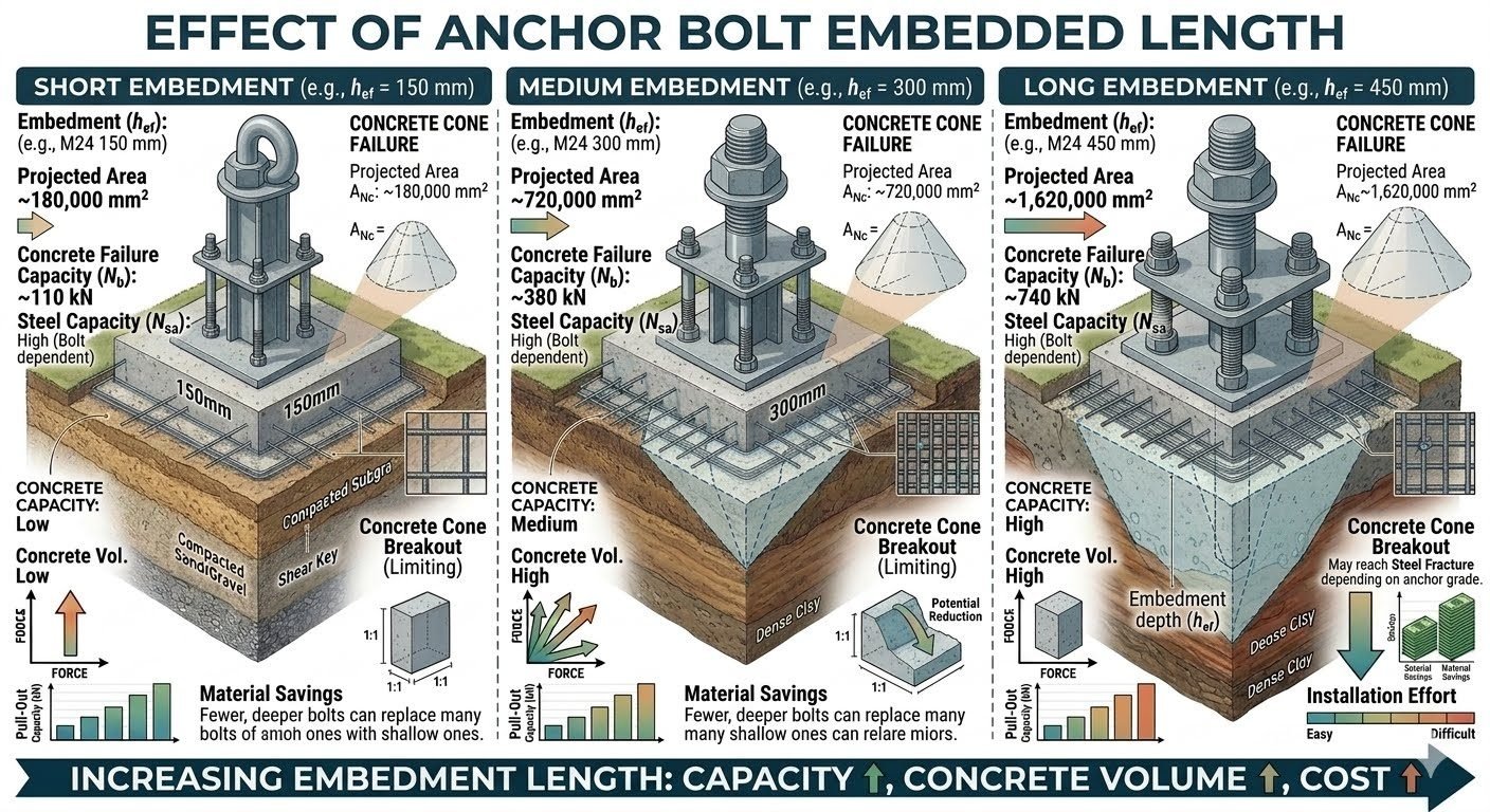
The embedment depth directly alters the tensile capacity governed by concrete breakout, side-face blowout, and steel yielding. By examining short embedment (h_ef = 150text{ mm}), medium embedment (h_ef = 300text{ mm}), and long embedment (h_ef = 450text{ mm}) configurations for standard M24 fasteners, we can establish rigorous design parameters that satisfy modern building codes and prevent catastrophic structural pull-out events.
Key Engineering Takeaways
- Embedment depth scaling expands the projected concrete failure area exponentially, directly increasing tensile pull-out resistance.
- Short embedments (h_ef = 150text{ mm}) are strictly governed by concrete cone breakout rather than steel tensile strength.
- Deep embedments allow engineers to consolidate fastener counts, replacing multiple shallow anchors with fewer, higher-capacity deep bolts.
- Strict adherence to ASCE and ACI 318 anchorage provisions ensures safety factors are maintained across all load cycles.
Anchor Bolt Embedded Length Mechanics and Code Equations
When designing anchorage for industrial equipment subjected to combined shear and tension, the embedded length (h_ef) acts as the primary geometric variable. In my design practice, I evaluate anchorage using the Concrete Capacity Design (CCD) method detailed in ACI 318. This method assumes that concrete tensile breakout forms an idealized pyramid or cone with a side length equal to 1.5h_ef projecting from the anchor head or embedded washer plate to the free concrete surface.
Let us examine the mathematical progression across three distinct embedment depths for an M24 anchor rod. The projected concrete failure area (A_Nc) scales quadratically with embedment depth, calculated theoretically as A_Nc = (9h_ef^2) for a single anchor far from edges. For a short embedment where h_ef = 150text{ mm}, the projected failure area is approximately 180,000text{ mm}^2. This limited surface area results in a nominal concrete breakout capacity (N_cb) of approximately 110text{ kN}. At this shallow depth, concrete cone failure is invariably the governing failure mode, leaving the high steel tensile capacity (N_sa) of the M24 bolt underutilized.
Critical Design Warning: Shallow Embedment Vulnerability
Short embedments (h_ef = 150text{ mm}) exhibit high sensitivity to cracking and spalling under vibratory loads from reciprocating compressors or pumps. Always verify that edge distances (c_a1) do not truncate the projected cone area, which would further degrade N_cb and require supplemental edge reinforcement.
Increasing the embedment depth to a medium tier where h_ef = 300text{ mm} (e.g., standard heavy-duty M24 structural embedment) drastically alters the behavioral dynamics. The projected concrete failure area expands quadratically to approximately 720,000text{ mm}^2. Consequently, the nominal concrete breakout capacity (N_cb) climbs to approximately 380text{ kN}. While concrete cone failure remains the nominal check parameter, we approach a transitional zone where the steel tensile capacity (N_sa) of the M24 carbon steel rod begins to govern or share capacity depending on the specified steel grade (e.g., ASTM F1554 Grade 55 or Grade 105).
Pushing the embedment to the long tier where h_ef = 450text{ mm} yields a massive projected area of approximately 1,620,000text{ mm}^2. The resulting concrete breakout capacity reaches approximately 740text{ kN}. At this substantial depth, the concrete cone breakout capacity exceeds the ultimate tensile strength of standard M24 steel cross-sections, meaning steel ductile failure (N_sa) becomes the governing design criterion. While this provides excellent pull-out resistance and high concrete volume engagement, it introduces severe installation challenges, including accurate template alignment during concrete pours and increased core-drilling or formwork complexity.
Mathematical Formulation of Concrete Breakout
The nominal concrete breakout strength in tension (N_cb) is determined by the fundamental equation prescribed in ACI 318:
N_cb = left(frac{A_Nc}{A_Nc0}right) psi_ed,N psi_c,N psi_cp,N N_b
Where A_Nc0 = 9h_ef^2 represents the projected concrete breakout area of a single anchor without edge influence, and N_b is the basic concrete breakout strength of a single anchor in cracked concrete, calculated as:
N_b = k_c lambda_a √(f’_c) h_ef^1.5
In this formulation, k_c = 7.0 for cast-in anchors, f’_c is the specified compressive strength of concrete in megapascals (MPa), and lambda_a accounts for normal-weight or lightweight concrete. Reviewing these equations confirms that increasing embedment depth (h_ef) introduces a 1.5 power multiplier on basic breakout strength while simultaneously expanding the area ratio term, explaining the rapid escalation in pull-out capacity from short to long embedment configurations.
Advantages of Deep Embedment
- Significantly higher concrete breakout capacity (N_cb), reducing the risk of catastrophic tensile pull-out.
- Allows foundation designers to consolidate fastener counts, replacing numerous shallow M24 bolts with fewer deep anchors.
- Provides superior resistance against cyclic fatigue and heavy vibrational loads generated by large rotating machinery.
- Engages deep, unconfined mass concrete foundations, bypassing surface-level micro-cracking and freeze-thaw damage zones.
- Shifts the failure mode from brittle concrete breakout to ductile steel yielding, satisfying modern seismic design philosophies.
Disadvantages & Limitations
- Substantially higher material and installation costs associated with longer steel rods and deeper formwork or core-drilling.
- Increased difficulty in maintaining precise vertical alignment and template tolerances during massive concrete pours.
- Higher risk of hitting internal reinforcing steel mats (rebar congestion), requiring careful clash detection during detailing.
- Deep embedments (h_ef = 450text{ mm} or greater) demand heavy handling equipment on site, slowing down construction velocity.
- Retrofitting deep anchor bolts in existing structures is extremely labor-intensive and structurally disruptive.
Centrifugal Compressor and Heavy Pump Skids
Rotating machinery skids in petrochemical facilities experience intense harmonic vibrations and dynamic overturning moments. Engineers specify medium (h_ef = 300text{ mm}) to long (h_ef = 450text{ mm}) embedment M24 anchor bolts to prevent fatigue-induced micro-cracking in the grout and concrete base. This deep anchorage ensures that dynamic cyclic loads are safely dissipated into the massive foundation block without fastener loosening.
High-Capacity Pipe Rack Column Bases
Process pipe racks carry heavy thermal loads, dead weights, and lateral wind forces that subject base plates to high eccentric tension. Utilizing optimized embedment depths (h_ef = 300text{ mm} to 450text{ mm}) ensures that the projected concrete breakout volume is large enough to resist combined uplift forces. This minimizes base plate thickness requirements and prevents costly concrete anchor pull-out failures during extreme weather events.
Vertical Pressure Vessels and Distillation Columns
Tall vertical columns are subjected to severe overturning moments driven by seismic acceleration and high wind shear forces. These towers require long embedment anchor bolts (h_ef = 450text{ mm}) or specialized chair-type anchor assemblies. The massive concrete cone breakout volume and high steel tensile capacity are essential to keep the vessel skirt securely anchored to the reinforced concrete pedestal under operating pressures.
Industrial Overhead Crane Runway Girders
Overhead crane bracket supports and runway columns experience high impact loads and cyclic braking forces that create severe uplift and shear reversals. Civil engineers rely on medium-to-deep embedment configurations to restrict joint slip and fatigue propagation. Proper embedment depth guarantees that the concrete foundation maintains compressive integrity under repeated heavy wheel loads.
Embedment Comparison Data Table: Performance Metrics by Depth
In my structural design practice, evaluating the mechanical trade-offs across different embedment depths requires rigorous comparison of projected failure areas and ultimate capacities. The engineering data table below contrasts short, medium, and long embedment configurations for standard M24 anchor bolts, illustrating how capacity scales with depth per ACI 318 provisions.
Reviewing these metrics clarifies why shallow installations remain susceptible to premature concrete cone breakout, whereas deeper embedments transition failure modes toward steel yielding. Each parameter directly influences base plate thickness and anchor layout optimization.
| Embedment Category | Embedment Depth (h_ef) | Projected Area (A_nc) | Concrete Capacity (N_cb) | Limiting Failure Mode |
|---|---|---|---|---|
| Short Embedment | 150 mm (M24) | 180,000 mm-squared | ~110 kN | Concrete Cone Breakout (N_c) |
| Medium Embedment | 300 mm (M24) | 720,000 mm-squared | ~380 kN | Transition / Concrete Cone |
| Long Embedment | 450 mm (M24) | 1,620,000 mm-squared | ~740 kN | Steel Yielding / Deep Cone |
The data confirms a non-linear capacity increase relative to embedment depth, driven directly by the squared proportionality of the projected concrete failure area.
Technical Mapping & Specifications Matrix
Navigating structural fastening design requires a unified understanding of material properties, governing standards, and failure criteria. The technical mapping matrix below correlates structural entities with their corresponding code requirements and analytical parameters as specified by ASME and ACI frameworks.
This matrix serves as a quick-reference engineering guide for verifying structural calculations against established industry benchmarks. Every parameter listed must be accounted for during finite element modeling and base plate design reviews.
| Structural Entity | Governing Standard | Primary Parameter | Design Significance |
|---|---|---|---|
| Anchor Bolt Steel (M24) | ASTM F1554 Gr. 55 | Yield Strength (f_y) | Governs tensile rupture and ductile failure limits. |
| Concrete Breakout | ACI 318 Chapter 17 | Embedment Depth (h_ef) | Determines projected failure cone volume and capacity. |
| Pullout Resistance | ACI 318 / ACI 355 | Bearing Area (psi) | Prevents localized bond failure and slip-out. |
| Base Plate Rigidity | AISC Design Guide 1 | Plate Thickness (t_p) | Ensures uniform load distribution to all anchors. |
Utilizing this matrix during preliminary engineering reviews helps eliminate discrepancies between fastener steel capacity and surrounding concrete breakout limitations.
Site Verification Checklist: Anchor Bolt Installation & Embedment Quality Control
Ensuring that anchor bolts achieve their calculated embedment depth on site is critical for structural integrity. In my field inspections, I rely on a structured verification checklist to prevent installation errors that could compromise concrete breakout capacity per ACI 318 specifications.
The following validation rules and site checkpoints must be systematically signed off by quality control engineers before concrete pouring and base plate grouting operations commence.
Field Inspection Protocol for Deep Embedment Anchors
- Pre-Pour Depth Verification: Measure and record the vertical distance from the top of the concrete formwork to the bottom of each anchor bolt template, verifying exact h_ef dimensions (150mm, 300mm, or 450mm).
- Template Rigidity Check: Confirm structural steel templates are securely braced against shifting or vibration during high-frequency concrete consolidation.
- Material Traceability: Inspect mill test reports for ASTM F1554 compliance, verifying grade markings on all installed M24 anchor rods.
- Edge Distance & Spacing: Verify that clear edge distances (c_ac) meet or exceed minimum requirements to prevent premature splitting failures in restrained foundations.
- Post-Pour Torque Inspection: Calibrate torque wrenches to specified values per AISC guidelines after concrete achieves 70% design compressive strength.
Rigid adherence to this checklist safeguards against costly remedial retrofits and guarantees that the installed fastener network performs in exact accordance with structural calculations.
Field Case Study: Real-World Application
During the expansion of a major petrochemical facility, our engineering team faced significant seismic overturning moments on heavy fractionator column base plates, prompting a complete re-evaluation of our anchor bolt embedment strategy.
Problem Statement: Shallow Embedment Vulnerability
The initial foundation design relied on a dense pattern of short M24 anchor bolts (h_ef = 150 mm) providing approximately 110 kN of concrete breakout capacity per anchor, which proved entirely inadequate under extreme wind and seismic loading combinations.
- Projected concrete failure areas overlapped significantly, causing severe group reduction effects.
- Concrete cone breakout governed the failure envelope, limiting overall structural capacity.
- Excessive congestion of reinforcing steel made concrete placement difficult and prone to honeycombing.
- Base plate thickness required unreasonable stiffeners to distribute loads evenly across the shallow fasteners.
Outcome: Optimized Long Embedment Retrofit
Transitioning to a reduced count of long embedment M24 anchor bolts (h_ef = 450 mm) boosted individual breakout capacity to ~740 kN, successfully resolving safety margins while streamlining foundation construction.
- Eliminated 60 percent of total anchor penetrations, drastically reducing material and drilling labor costs.
- Expanded the projected concrete failure area to 1,620,000 mm-squared per anchor, eliminating group interaction penalties.
- Shifted the governing failure mode from brittle concrete breakout to ductile steel yielding per ACI 318 standards.
- Improved concrete consolidation around deep embedment rods by relieving rebar congestion in the footing.
Recommendation: For heavy industrial equipment foundations subject to high dynamic overturning moments, always prioritize deeper embedment configurations over high-density shallow fastener layouts to achieve superior safety and structural economy.
Frequently Asked Engineering Questions
How does doubling the anchor bolt embedment length affect concrete breakout capacity?
- Concrete cone failure capacity proportional to the 1.5 power of embedment depth.
- Projected failure area quadruples when embedment depth doubles.
- Ultimate tensile breakout capacity increases significantly but remains governed by edge distances.
When should an engineer specify a long embedment over multiple short anchor bolts?
- Reduces baseplate dimensions by transmitting higher loads through fewer anchorage points.
- Minimizes rebar congestion inside heavily reinforced concrete pedestals.
- Lowers overall installation labor hours despite requiring deeper core drilling or sleeves.
What limits the tensile capacity of a medium embedment M24 anchor bolt?
- Concrete cone breakout capacity hovers near 380 kN depending on edge constraints.
- Steel tensile strength (N_sa) of an M24 carbon steel bolt begins approaching the breakout limit.
- Cracking in unreinforced foundation blocks can trigger premature breakout failure.
How does concrete compressive strength influence short versus long embedment designs?
- Short embedment bolts benefit moderately from higher f’c but remain volume-limited.
- Long embedment bolts achieve massive absolute capacity gains in high-strength concrete mixes.
- Low-strength concrete forces excessive embedment depths to reach required tension resistance.
What installation challenges arise when specifying long embedment anchor bolts?
- Drill bit wander increases dramatically over 450 mm, causing baseplate misalignment.
- Interference with bottom layer reinforcing steel requires meticulous shop drawing coordination.
- Ensuring complete epoxy or grout encapsulation becomes difficult in deep, narrow holes.
- If designing dynamic pump foundations subject to cyclic uplift, choose long embedment (h_ef = 450 mm) M24 bolts to shift the failure mechanism away from brittle concrete breakout toward ductile steel yielding.
- When working with constrained foundation thicknesses or congested reinforcement cages, specify medium embedment (h_ef = 300 mm) configurations paired with supplementary edge reinforcement to optimize material volume without triggering breakout failures.
- Avoid short embedment (h_ef = 150 mm) bolts for primary structural column baseplates experiencing overturning moments, as the limited 180,000 mm-squared projected failure area creates an unacceptably high risk of sudden concrete cone separation.
- Always verify that contractor drilling tolerances on site account for the cumulative deviation of deep embedment shafts before pouring thick concrete pedestals to prevent costly baseplate re-machining.
Complete Course on
Piping Engineering
Check Now
Key Features
- 125+ Hours Content
- 500+ Recorded Lectures
- 20+ Years Exp.
- Lifetime Access
Coverage
- Codes & Standards
- Layouts & Design
- Material Eng.
- Stress Analysis
