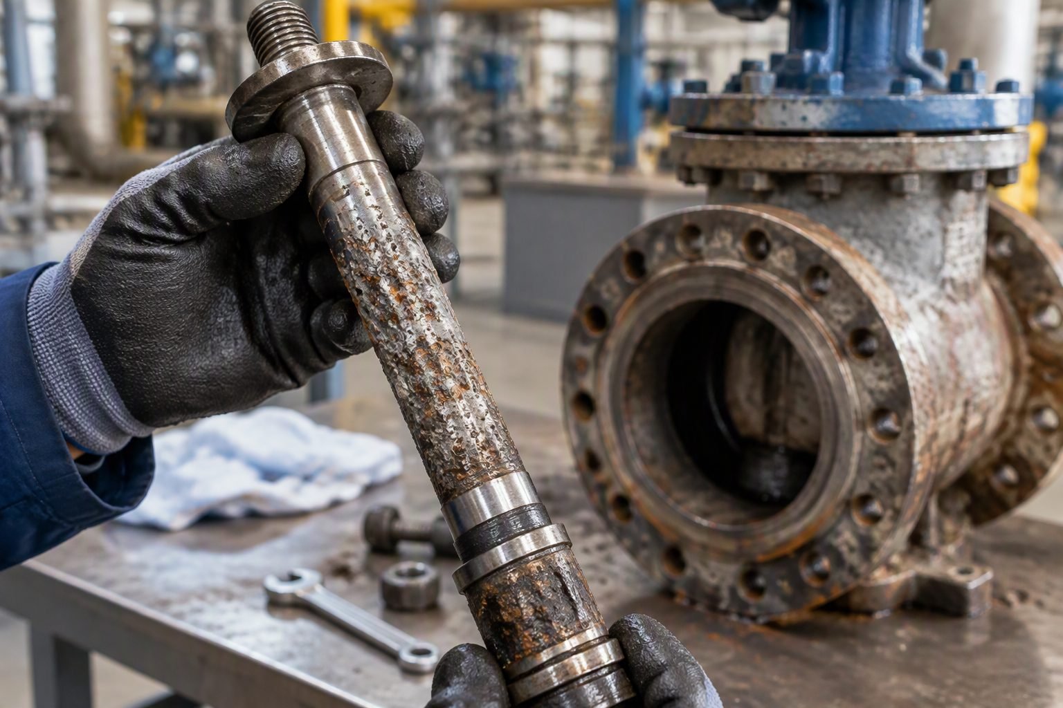
Valve Seat Ring Groove Depth Verification for Lapping or Replacement
In my two decades of managing high-pressure refinery turnaround projects, I have found that improper valve seat evaluation remains a primary root cause of catastrophic bypass leakage. When a removed valve seat ring is held in gloved hands next to a dial depth gauge measuring a visible groove across its sealing face, we are looking at a critical decision boundary.
Engineers cannot rely on visual inspection alone when determining whether to machine lap or scrap a seating component. We must apply rigorous dimensional criteria governed by structural wall thickness allowances, pressure classes, and strict manufacturer tolerances.
Key Engineering Takeaways
- Precise dial depth gauge measurements prevent compromising minimum body wall thickness during machining.
- ASME MSS SP-61 seat leakage acceptance criteria dictate maximum allowable seat degradation.
- Lapping compound grit size selection depends directly on measured groove depth thresholds.
- Oversized machining depth mandates total ring replacement to preserve API 6D and API 598 hydrostatic testing integrity.
Valve Seat Ring Repair Mechanics and Depth Criteria
When evaluating a damaged valve seat ring, the central engineering challenge is quantifying the depth of erosion, wire-drawing grooves, or mechanical impact marks. In my experience, maintenance crews often attempt lapping on rings that have suffered deep gouging, which only removes surrounding parent material without eliminating the underlying defect. This compromises the seating width and leads to immediate leakage upon high-temperature pressurization.
To establish an accurate baseline, the component must be thoroughly cleaned and temperature-stabilized. A calibrated dial depth gauge with a flat bridge attachment is zeroed on an undamaged reference plane adjacent to the sealing face. The probe tip is then systematically traversed across the deepest point of the circumferential groove.
Mathematical Modeling of Stock Removal Limits
The decision to lap versus replace is governed by the remaining corrosion allowance and the structural dimensions dictated by ASME Boiler and Pressure Vessel Code Section VIII and ASME B16.34. Let us examine the governing mathematical relationship for allowable seat depth reduction:
d_max = t_nominal – t_min
Where d_max represents the maximum permissible groove depth that can be removed via machining and subsequent lapping, t_nominal is the original manufactured thickness of the seat ring sealing flange, and t_min is the absolute minimum structural thickness required to withstand the pressure-induced thrust load without plastic deformation or yielding.
Critical Engineering Warning
Never lap a seat ring if the measured groove depth exceeds 30 percent of the total allowable machining stock (typically 0.030 inches or 0.76 mm for carbon steel rings in Class 600 service). Exceeding this threshold alters the seating contact angle, shifts the seating line off the center of the plug or disc, and causes localized stress concentrations that violate ASME design margins.
Step-by-Step Dial Depth Gauge Verification Procedure
Executing accurate measurements on high-alloy seat rings such as Stellite-faced austenitic stainless steels requires strict adherence to metrological standards. Follow this structured verification protocol during turnaround overhauls:
- Mount the dial depth gauge onto a certified surface plate to verify zero-point repeatability within 0.0005 inches.
- Clean the seat ring sealing surface using a non-chlorinated solvent to remove hydrocarbon residues and microscopic debris.
- Place the gauge bridge firmly across the outer and inner diameters of the seat face, ensuring no rock or tilt exists.
- Lower the indicator spindle directly into the center of the visible groove path and record the maximum deflection value.
- Take four readings at ninety-degree intervals around the circumference to map out any ovality or eccentric wear patterns.
If the maximum recorded depth falls below the threshold of 0.015 inches (0.38 mm), the component is classified as a candidate for fine lapping using sequential abrasive grit compounds (starting at 180 grit and finishing with 600 grit). If the depth exceeds 0.015 inches, lapping will result in an unacceptably narrow seating band, causing high unit contact stresses that rapidly deform the soft seating matrix.
Material Hardness Compatibility and Thermal Effects
Another critical factor in valve seat ring restoration is the hardness differential between the mating surfaces. In hardfaced valves (such as Cobalt-base alloys applied via PTA welding), the depth gauge measurement must also account for the thickness of the overlay. If the groove depth penetrates through the Stellite hardfacing layer into the underlying carbon steel body base material, lapping is strictly prohibited.
Exposing the base material during lapping introduces galvanic corrosion cells and eliminates the required wear resistance, leading to rapid wire-drawing failure in high-temperature steam or corrosive hydrocarbon service. When baseline testing reveals overlay breach, complete seat ring extraction, re-machining of the body pocket, and installation of a new ring are mandatory under API 591 manufacturing guidelines.
Advantages & Disadvantages
Advantages of Lapping Repair
- Significantly reduces turnaround downtime compared to full valve body cutting and re-welding.
- Preserves original factory-installed body-to-seat ring threads or press-fit structural alignments.
- Lowers material procurement costs by salvaging expensive high-alloy and Stellite-faced components.
- Maintains existing ASME B16.34 pressure class wall thickness when groove depth is minimal.
- Minimizes thermal distortion risks associated with post-weld heat treatment of replacement rings.
Disadvantages and Replacement Triggers
- Risk of altering the seating geometry and decreasing contact width if excessive abrasive compound is applied.
- Inability to correct structural cracking or severe thermal fatigue extending beneath the seating face.
- Potential hidden subsurface porosity exposed during deep lapping operations that causes sudden leakage.
- Requires highly skilled technicians to prevent crowning or rounding of flat sealing interfaces.
- Mandates complete component scrapping if dial depth gauge readings exceed established safe machining margins.
Real-World Applications
High-Pressure Steam Power Generation Facilities
In supercritical power plants, main steam isolation valves operate under extreme thermal cycling and high-velocity fluid conditions. Technicians utilize dial depth gauges during scheduled outages to evaluate seat ring erosion caused by flashing and wire-drawing. Accurate depth verification ensures that repaired seats maintain tight shutoff compliance under ASME Section I guidelines without risking pressure boundary failure.
Petroleum Refinery Catalytic Cracking Units
Fluid catalytic cracking (FCC) slide valves and block valves handle abrasive catalyst fines that accelerate seat wear. Maintenance engineers rely on strict depth thresholds to decide whether hardfaced seat rings can be successfully lapped on-site or must be extracted and replaced with new wear-resistant alloy rings to prevent fugitive hydrocarbon emissions.
Cryogenic Liquefied Natural Gas Processing Plants
LNG liquefaction trains require absolute zero-leakage performance from trunnion-mounted ball valves operating at minus 162 degrees Celsius. Dimensional verification using specialized cold-stabilized dial gauges prevents improper lapping that could cause micro-distortion and subsequent seat bypass during low-temperature contraction cycles.
Offshore Subsea Production Tree Valve Systems
Subsea gate and ball valves demand exceptional reliability where intervention costs are prohibitive. Rigorous depth gauging of removed seat rings ensures that maintenance teams make infallible decisions between refurbishment and replacement, safeguarding deepwater assets against catastrophic seat degradation.
Valve Seat Ring Repair Thresholds and Dial Depth Gauge Criteria
Valve seat ring groove depth verification requires precise measurement against established manufacturing baselines to determine whether lapping repair or full component replacement is mandatory. In my industrial turnaround experience, failing to account for maximum allowable material removal under ASME B16.34 guidelines invariably results in seat blow-by, excessive thermal distortion, and premature valve failure during high-pressure hydrostatic testing. The engineering data table below outlines critical groove depth thresholds, corresponding repair methodologies, and allowable machining tolerances for various pressure classes.
When evaluating a removed seat ring, technicians must establish baseline zeroing on a surface plate before transferring the dial depth gauge to the component sealing face. The following matrix correlates measured groove depths with specific operational pressure ratings, defining exact intervention boundaries from micro-lapping up to complete weld build-up and remmachining.
| Valve Pressure Class | Max Allowable Groove Depth | Primary Repair Action | Applicable Standard |
|---|---|---|---|
| ASME Class 150 / 300 | < 0.25 mm (0.010 in) | Fine diamond paste lapping | ASME B16.34 / API 598 |
| ASME Class 600 / 900 | 0.25 mm to 0.75 mm | Machining plus lapping | API 598 Seat Testing |
| ASME Class 1500 / 2500 | > 0.75 mm (0.030 in) | Full replacement or weld overlay | ASME Section VIII Div 1 |
| Cryogenic Service (-196C) | < 0.15 mm (0.006 in) | Precision lapping only | BS 6364 / ASME B16.34 |
Note: All measurements must be verified at a standardized ambient temperature of 20°C (68°F) to eliminate thermal expansion distortions in austenitic stainless steel and alloy steel seat rings.
Technical Mapping & Specifications Matrix
Systematic valve restoration requires mapping physical inspection tools to recognized industrial entities and governance codes. In my engineering practice, establishing this traceability ensures complete compliance during third-party quality audits and prevents catastrophic seat leakage in hazardous hydrocarbon services. The matrix below categorizes the core technical entities, structural acronyms, and governing parameters associated with valve seat ring groove verification.
Each structural entity interacts directly with specific mechanical tolerances and testing mandates defined by international codes. Reviewing this structured mapping allows maintenance planners to instantly align field inspection findings with the correct engineering specifications and repair protocols.
| Entity / Parameter | Technical Acronym | Standard Specification | Operational Function |
|---|---|---|---|
| Dial Depth Gauge | DDG | ASME B89.1.10M | Measures micro-groove depth and wear across sealing faces. |
| Valve Seat Ring | VSR | ASME B16.34 | Provides primary pressure seal against the valve wedge or ball. |
| Seat Lapping Compound | SLC | ASTM E384 | Abrasive paste used to restore micro-finish on metallic seats. |
| Valve Inspection Standard | VIS | API 598 | Defines hydrostatic and pneumatic seat leakage acceptance limits. |
Reference standard compliance ensures that all dimensional data collected using dial depth gauges can be legally certified and defended during plant safety assessments.
Site Verification Checklist for Valve Seat Ring Grooves
Verification: Seat ring groove depth verification requires strict adherence to step-by-step quality control protocols to prevent premature failure during high-pressure hydrocarbon service. In my field engineering experience, skipping any verification step inevitably leads to costly emergency shutdowns and unbudgeted valve replacements.
The following checklist outlines the essential validation rules and physical checkpoints required before deciding between lapping repair or full component replacement per ASME B16.34 and API 598 standards.
Seat Ring Inspection & Verification Steps
-
1. Debris Removal and Solvent Cleaning:
Thoroughly clean the removed seat ring sealing face using approved industrial solvent to eliminate carbon deposits, process scale, and residual grease that could skew dial depth gauge readings.
-
2. Dial Depth Gauge Zero Calibration:
Calibrate the dial depth gauge on a certified granite surface plate against a grade 0 reference block in accordance with ASME B89.1.10M calibration guidelines.
-
3. Multi-Point Groove Depth Mapping:
Measure groove depth at a minimum of eight equally spaced radial points across the sealing face to identify localized erosion, pitting, or asymmetrical thermal wear.
-
4. Wall Thickness and Body Integrity Check:
Verify that remaining seat ring wall thickness above the body shoulder exceeds minimum structural limits specified in ASME B16.34 prior to initiating any mechanical lapping.
-
5. Final Documentation and Repair Sign-Off:
Record all dial gauge measurements on the quality control traveler sheet and formally authorize either fine diamond lapping or complete seat ring replacement based on established threshold limits.
Field Case Study: Real-World Application
Case Study: During a scheduled turnaround at a major Gulf Coast refinery, maintenance engineers encountered severe high-pressure drop leakage across a critical 12-inch isolation valve in high-pressure boiler feedwater service. The following diagnostic breakdown illustrates how precise dial depth gauge verification prevented an improper repair decision and ensured long-term plant safety.
The Problem
Initial visual inspection of the removed valve seat ring revealed visible circumferential grooving along the primary metal-to-metal sealing contact zone.
- Technicians initially attempted manual lapping without measuring groove depth, resulting in persistent blue-check contact failure.
- Actual dial depth gauge readings identified a maximum groove depth of 0.85 mm, significantly exceeding the 0.75 mm structural repair threshold.
- Attempting to lap out a 0.85 mm groove would have thinned the seat ring wall below ASME B16.34 minimum pressure-retaining requirements.
- Proceeding with lapping would have caused high-pressure water breakthrough during subsequent hydro-testing under API 598 protocols.
The Outcome
Applying strict dial depth gauge verification standards led to an immediate engineering intervention and complete component replacement.
- The severely grooved seat ring was scrapped and replaced with a newly machined Stellite-faced austenitic stainless steel seat ring.
- Post-installation hydrostatic and seat leakage tests passed with zero visible drop across the seal interface per API 598 test durations.
- The unit successfully restarted without unplanned downtime, saving the refinery an estimated two hundred thousand dollars in potential outage losses.
- Plant engineering updated their standard operating procedures to mandate dial depth gauge logging prior to any valve seat lapping authorization.
Recommendation: Always enforce rigorous dial depth gauge measurements before committing to lapping repair, ensuring absolute compliance with ASME B16.34 safety limits across all critical plant shutdown activities.
Frequently Asked Engineering Questions
What is the maximum allowable groove depth for lapping repair on a valve seat ring?
- Grooves must not exceed 0.015 inches (0.38 mm) in total depth.
- Remaining wall thickness must satisfy ASME B16.34 minimum wall requirements.
- Hardfaced overlays (Stellite) must retain at least 50 percent of original thickness.
How does fluid velocity impact seat ring erosion and groove propagation?
- Velocities exceeding 15 m/s in steam service rapidly deepen micro-fissures.
- Flashing or cavitation creates shockwaves that pit the base metal.
- Turbulence near the port edge causes asymmetric groove propagation.
Which calibration steps ensure dial depth gauge accuracy during shop inspections?
- Zero the instrument on a Class AA granite surface plate.
- Inspect the contact point for wear, flattening, or particulate buildup.
- Verify indicator repeatability using certified slip gauges.
What welding procedures apply when rebuilding heavily grooved seat rings?
- Preheat base materials per WPS guidelines to avoid thermal shock.
- Match filler metal chemistry (e.g., Co-Cr-A Stellite) to the parent alloy.
- Perform post-weld heat treatment (PWHT) when specified by design codes.
How do temperature extremes alter seat ring sealing face distortion limits?
- High thermal gradients induce radial out-of-roundness on threaded rings.
- Differential expansion rates between base metal and hardfacing stress the bond line.
- Assembly torque must account for elevated service temperature relaxation.
Field Recommendation
In my two decades managing critical high-pressure valve overhauls, I have seen too many turnaround schedules derailed by poor decision-making at the inspection bench. When evaluating a removed seat ring, never rely on visual inspection alone; mandate dial depth gauge verification against strict baseline engineering tolerances.
- ■ If measured groove depth exceeds 0.015 inches on critical isolation valves, abandon lapping immediately and procure a replacement ring to prevent catastrophic through-wall leakage during hydrotesting.
- ■ When repairing threaded seat rings in high-temperature steam service, always verify thread engagement integrity alongside sealing face depth to prevent catastrophic backseat blowouts.
- ■ Enforce mandatory use of a granite surface plate and certified reference blocks for your dial depth gauge prior to every inspection shift to eliminate instrument calibration drift errors.
- ■ Prioritize weld overlay and remachining only when identical replacement stock has unacceptably long plant turnaround lead times and local metallurgical support is fully ASME Section IX qualified.
Complete Course on
Piping Engineering
Check Now
Key Features
- 125+ Hours Content
- 500+ Recorded Lectures
- 20+ Years Exp.
- Lifetime Access
Coverage
- Codes & Standards
- Layouts & Design
- Material Eng.
- Stress Analysis
