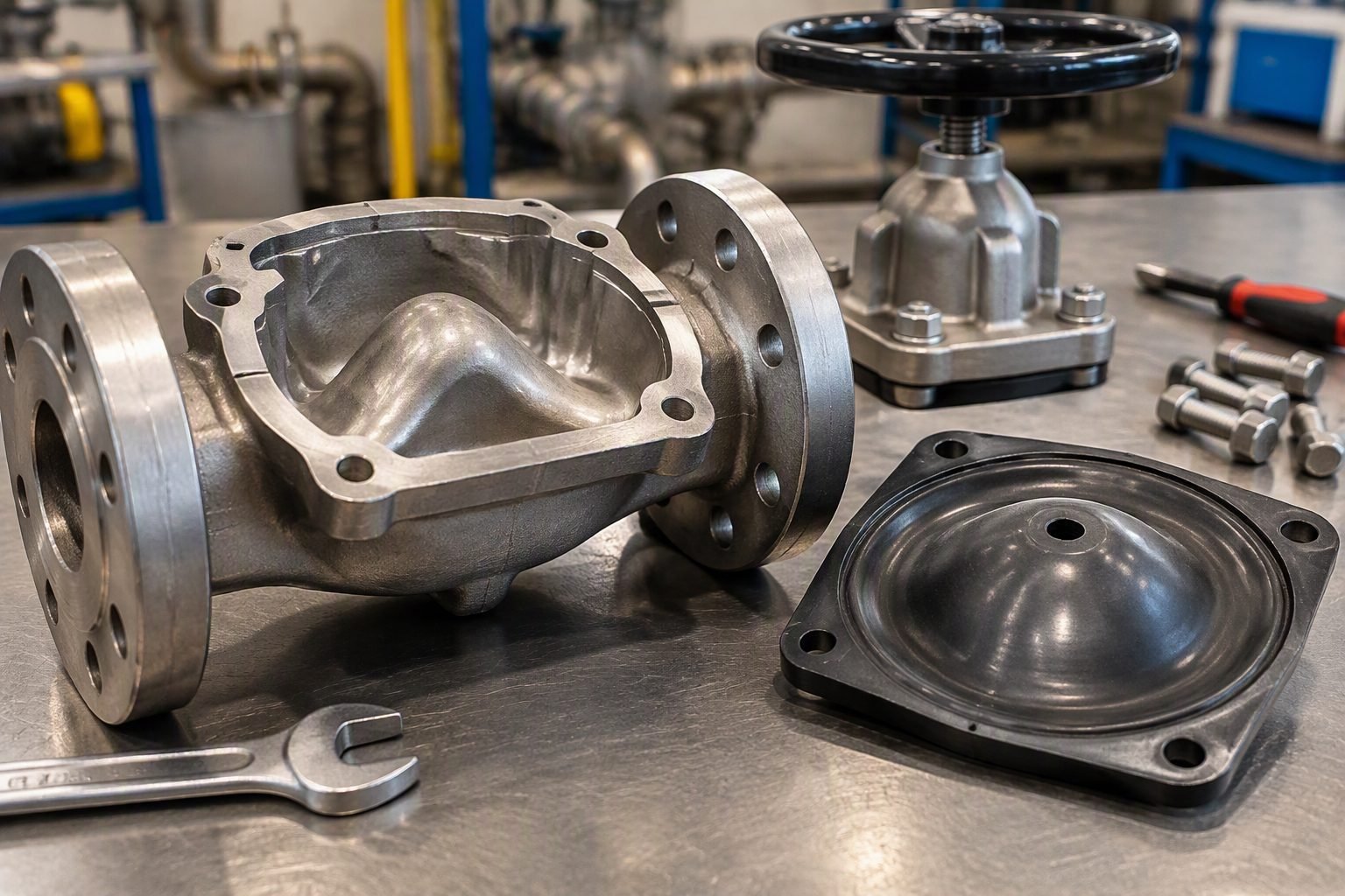
Valve Trim Repair vs Replacement: Engineering Evaluation Guide
In my two decades managing critical piping and control systems across refining and petrochemical facilities, I frequently walk into our maintenance workshops to find technicians staring at a pair of control valve plugs. One sits freshly lapped with mirror-finish stellite seating surfaces, while its counterpart displays severe wire-drawing grooves, cavitation pitting, and diminished wall thickness. Making the correct repair-versus-replace decision for valve trim repair is not merely a matter of workshop preference. It requires rigorous calculation, adherence to ASME standards, and a clear-eyed evaluation of total lifecycle costs.
When high-pressure drops flash process fluids or entrained catalyst fines erode guide bushings, control valve trim takes the brunt of the fluid kinetic energy. Deciding whether to weld-build and machine worn components or order a complete OEM replacement set dictates both your immediate maintenance budget and your next unscheduled outage risk. Let us explore the engineering parameters that govern this critical decision process.
Key Engineering Takeaways
- Establish minimum wall thickness limits per ASME B16.34 guidelines before undertaking weld reclamation.
- Evaluate metallurgy compatibility; high-nickel alloys and hardfacings like Stellite 6 demand specialized post-weld heat treatment.
- Calculate total cost of ownership by factoring in downtime risks alongside raw material replacement costs.
Engineering Evaluation for Valve Trim Repair and Replacement
Evaluating whether to execute valve trim repair or complete replacement begins with a meticulous physical and metallurgical examination. When control valves experience high-velocity fluid flow, pressure drops frequently trigger flashing or cavitation. The resulting shock waves strip away protective oxide layers, leading to rapid material loss on plugs, cages, and seat rings.
To determine if a component can undergo valve trim repair, we must first measure the remaining wall thickness against the manufacturer baseline and design drawings. The primary governing rule comes from ASME B16.34, which mandates that pressure-retaining and guiding surfaces must never fall below the calculated minimum wall thickness plus structural corrosion allowances.
Critical Safety Warning
Never attempt weld overlay reclamation on valve trim components where base metal pitting has penetrated beyond 30% of the total wall thickness. Structural distortion during welding combined with high thermal stresses can lead to sudden catastrophic stem or plug failure under operational pressure differentials.
Metallurgical Considerations and Hardfacing Integrity
Most heavy-duty control valve plugs and seats are fabricated from austenitic stainless steels (such as ASTM A182 F316) or martensitic grades (like ASTM A476 or 410 stainless), overlaid with cobalt-based alloys like Stellite 6 or nickel-based alloys. When these surfaces erode, simple machining is often insufficient.
During valve trim repair, technicians frequently use Gas Tungsten Arc Welding (GTAW) to restore lost cobalt-based hardfacing. However, strict pre-heat and post-weld heat treatment (PWHT) protocols must be followed to prevent micro-fissuring in the heat-affected zone. If the base material has suffered extensive thermal cycling fatigue, re-machining will expose brittle grain structures that fail ANSI/FCI 70-2 leakage class standards rapidly.
Clearance Tolerances and Guide Bushing Wear
Control valve performance relies heavily on precise diametral clearances between the plug guiding surfaces and the cage or body guide bushings. Standard engineering practice dictates that guide clearances must be maintained within tight tolerances, typically between 0.05 mm and 0.15 mm depending on valve size and operating temperature.
When evaluating valve trim replacement versus repair, excessive side-play in the guide bushings indicates that local boring and bushing replacement is required. If the plug stem itself has worn unevenly due to side-loading from the actuator yoke, truing the stem on a lathe may reduce its diameter below the minimum buckling load threshold calculated using Euler beam formulas for high-thrust actuator applications.
Cost-Benefit Analysis and Lifecycle Economics
Plant turnaround managers often face aggressive schedules where valve trim repair appears more attractive due to immediate availability compared to long-lead OEM replacement parts. However, a true lifecycle cost evaluation must account for mean time between failures (MTBF).
If a reconditioned trim set achieves only 50% of the operational lifespan of a new OEM component, the cost of the subsequent unscheduled shutdown far outweighs initial material savings. Conversely, for non-critical utility services operating at low pressure drops, professional machining and lapping offer significant economic advantages.
Advantages & Disadvantages
Advantages of Repair
- Significantly reduced lead times compared to custom OEM replacement manufacturing cycles.
- Lower direct material acquisition costs for expensive high-alloy components.
- Preservation of existing valve body body-bonnet alignment and baseline piping geometry.
- Opportunity to upgrade worn hardfacing to superior cobalt or nickel alloys during weld reclamation.
- Immediate utilization of internal workshop capabilities for rapid turnaround during plant outages.
Disadvantages of Repair
- Risk of residual welding stresses causing micro-cracking and premature mechanical failure.
- Inability to restore original metallurgical fatigue limits once base metal has thinned significantly.
- Potential loss of tight ANSI/FCI 70-2 shut-off class rating if lapping precision is compromised.
- Shorter operational lifespan between overhauls compared to factory-new OEM trim sets.
- Higher quality control overhead required for non-destructive examination (NDE) of weld repairs.
Real-World Applications
High-Pressure Boiler Feedwater Control Valves
Boiler feedwater regulating valves experience severe liquid flashing and high pressure drops across multi-stage cage trim. When erosion degrades the inner plug shoulders, precision valve trim repair using Stellite 6 weld overlay restores flow characteristics without requiring costly multi-week valve body replacement.
Engineering teams perform rigorous liquid penetrant testing (PT) post-machining to verify defect-free surfaces capable of withstanding 250 bar operating pressures.
Catalytic Cracker Catalyst Slurry Letdown Service
Fluid catalytic cracking units expose letdown valves to abrasive catalyst fines moving at high velocities, wearing away trim walls rapidly. Due to extreme replacement costs for proprietary exotic alloy sets, specialized tungsten carbide thermal spray coatings are applied during scheduled maintenance turnarounds.
This hybrid repair methodology extends run lengths between scheduled turnarounds by hardening the substrate against abrasive particulate wear.
Cryogenic LNG Liquefaction Process Control
Liquefied natural gas facilities operate control valves at extreme sub-zero temperatures where material embrittlement is a primary concern. Valve trim repair in these applications demands precise dimensional restoration and cryogenic thermal shock testing.
Full OEM replacement is frequently mandated by safety standards if wall thickness measurements breach strict ASME B16.34 low-temperature design margins.
High-Temperature Steam Turbine Bypass Systems
Power generation turbine bypass valves handle superheated steam exceeding 550 degrees Celsius, causing severe thermal fatigue and seat distortion. Technicians evaluate trim repair by measuring seat ring ovality and checking for thermal stress cracking along the plug contours.
When deformation exceeds allowable diametral tolerances, complete trim replacement with precipitation-hardened stainless steel ensures reliable emergency trip operation.
Chemical Plant Corrosive Acid Throttling Services
Chlor-alkali and acid processing plants utilize high-alloy trim materials such as Hastelloy C-276 and Titanium to resist chemical attack. Because welding reactive or nickel-rich alloys requires inert gas chambers and specialized filler metals, valve trim repair is often restricted to light mechanical polishing.
Deep pitting in these corrosive environments automatically triggers immediate component replacement to prevent sudden containment failure and hazardous chemical release.
Valve Trim Repair vs Replacement Engineering Parameters
When executing maintenance on critical process control valves, maintenance engineers must evaluate physical wear against strict wall thickness thresholds defined in ASME B16.34 and API 598 standards. The engineering data table below provides a rigorous quantitative comparison between reconditioning worn components through specialized hardfacing and procuring entirely new trim sets.
Reviewing these operational parameters helps prevent catastrophic pressure boundary failures, cavitation damage, and premature seal degradation across severe service applications.
| Parameter / Metric | Reconditioned Trim (Repair) | New Replacement Trim | Governing Code / Standard |
|---|---|---|---|
| Minimum Wall Thickness | Greater than 87.5 percent of nominal design baseline | 100 percent nominal manufacturing thickness | ASME B16.34 |
| Hardfacing Thickness | Restored to 1.5 mm minimum overlay depth | Factory-applied 2.0 mm Stellite 6 deposit | AWS A5.13 |
| Seat Leakage Class | Class IV or V after precision lapping | Class VI bubble-tight shutoff capability | FCI 70-2 |
| Hydrostatic Test Pressure | 1.5 times maximum allowable working pressure | 1.5 times maximum allowable working pressure | API 598 |
| Lead Time & Logistics | 3 to 5 business days in local workshop | 12 to 24 weeks OEM factory delivery | Internal Plant Metric |
Table 1: Quantitative evaluation matrix comparing reconditioned valve trim components against new OEM replacements under ASME and API regulatory frameworks.
Technical Mapping & Specifications Matrix
To maintain absolute traceability during control valve overhauls, reliability engineers must map physical hardware parameters to recognized industry specifications. The entity matrix below breaks down the critical metallurgical designations, testing protocols, and mechanical tolerances associated with valve trim repair and replacement workflows.
Each entry cross-references global engineering standards established by organizations such as ASTM International and the International Organization for Standardization.
| Entity / Component | Standard Designation | Primary Physical Parameter | Acceptance Criteria |
|---|---|---|---|
| Plug & Stem Assembly | ASTM A276 Type 316 | Surface Hardness & Concentricity | Minimum 35 HRC post-treatment; runout under 0.05 mm |
| Seat Ring Overlay | AWS A5.13 CoCr-A | Cobalt-based Alloy Deposition | Zero porosity via liquid penetrant inspection |
| Body Cavity Pressure | API 598 Section 4 | Shell Hydrostatic Integrity | No visible leakage during 3-minute dwell time |
| Dimensional Tolerances | ISO 5208 Rate A | Seating Surface Clearance | Exact alignment within 0.02 mm radial tolerance |
Table 2: Comprehensive entity mapping defining material standards, physical parameters, and quality acceptance criteria for valve trim maintenance.
Valve Trim Repair Site Verification Checklist
Executing a successful control valve turnaround requires a methodical, step-by-step verification process before reinstalling reconditioned trim components into high-pressure piping loops. In my experience across major refinery overhauls, skipping intermediate inspection gates inevitably leads to premature seat leakage and unplanned shutdowns.
Use the structured verification checklist below to validate that every component meets rigorous mechanical and metallurgical standards before returning equipment to active service.
Pre-Installation Quality Control Protocol
- Decontamination & Cleaning: Verify that all valve body cavities and trim components are thoroughly grit-blasted and solvent-cleaned to remove residual process scaling and hydrocarbons per SSPC-SP 10 standards.
- Ultrasonic Thickness Testing: Measure plug skirt and seat ring wall thickness using calibrated UT equipment, ensuring remaining metal exceeds 87.5 percent of nominal baseline.
- Liquid Penetrant Examination: Inspect all freshly machined hardfacing and weld overlays for surface cracking or micro-fissures in accordance with ASME Section VIII Division 1 Appendix 8.
- Blue-Checking Seating Surfaces: Apply engineer’s blue dye to verify 360-degree continuous contact between the plug face and seat ring prior to final torque application.
- Stem Straightness & Runout: Check valve stem radial runout using dial indicators mounted on V-blocks, confirming total indicated runout remains below 0.05 mm.
- Hydrostatic Shell & Seat Testing: Perform hydrostatic pressure testing following API 598 to validate seat tightness and packing gland integrity under load.
Following this rigorous site checklist ensures complete compliance with plant safety management systems and drastically reduces the probability of premature valve failure.
Field Case Study: Real-World Application
In high-pressure hydroprocessing units, deciding whether to execute valve trim repair or procure new components directly impacts turnaround schedules and plant profitability. A recent overhaul project at a Gulf Coast refinery highlights the critical engineering evaluation required when handling severely damaged control valve internals.
Case Problem: Severe Cavitation and Wall Thinning in a Letdown Valve
A 6-inch angle control valve handling high-pressure reactor effluent experienced severe trim degradation, threatening plant throughput during a scheduled 14-day turnaround window.
- Deep cavitation pitting penetrated 20 percent of the plug skirt cross-section, approaching the minimum structural thickness limit.
- OEM replacement trim quoted an 18-week lead time, which would have forced an extended, multi-million dollar unscheduled plant outage.
- Seat ring sealing faces exhibited deep erosion channels, causing severe bypass leakage that violated environmental emissions guidelines.
- Time constraints prohibited complete body replacement, necessitating an immediate engineering assessment for local workshop restoration.
Case Outcome: Successful Workshop Restoration and On-Time Startup
By conducting rigorous ultrasonic testing and deploying specialized welding procedures, the engineering team successfully restored the valve trim within the critical path window.
- Engineers applied automated Stellite 6 hardfacing via gas tungsten arc welding, rebuilding worn sealing surfaces beyond baseline thickness requirements.
- Post-weld heat treatment and precision CNC machining restored plug contour and stem concentricity within strict ASME B16.34 tolerances.
- Hydrostatic and seat leak testing confirmed Class V shutoff performance, exceeding plant specifications and satisfying API 598 protocols.
- The repaired valve returned to service on schedule, saving 450,000 in procurement costs and avoiding two months of production downtime.
Engineering Recommendation: Always perform ultrasonic thickness mapping before committing to scrap worn valve trim. When remaining metal exceeds 87.5 percent of nominal dimensions, specialized welding and precision machining offer a viable, code-compliant alternative to lengthy OEM replacements.
Frequently Asked Engineering Questions
What defines the minimum wall thickness threshold for valve trim components under ASME standards?
Minimum thickness limits are dictated by ASME B16.34 and ASME BPVC Section VIII, establishing boundaries for pressure containment and mechanical stress survival.
- Component walls must maintain at least 87.5 percent of nominal design thickness after machining.
- Corrosion allowances must never be compromised by restorative weld overlays or aggressive grinding passes.
- Ultrasonic testing measurements must verify structural integrity before any surface restoration work begins.
When should an engineer choose weld buildup over a complete valve trim replacement?
Weld buildup is economically viable for high-alloy components where base metal costs exceed machining labor, provided strict metallurgical rules are followed.
- The parent alloy must be weldable without inducing severe cracking or requiring complex post-weld heat treatment.
- Total depth of degradation must not exceed 30 percent of the total cross-sectional component thickness.
- Lead times for procurement of a new replacement trim set must exceed the turnaround window of the turnaround.
How does cavitation damage impact the decision to repair versus replace valve plugs and seat rings?
Severe cavitation creates deep sponge-like pitting that compromises material fatigue strength, often rendering surface-only repairs ineffective.
- Pitting depth exceeding two millimeters on seating surfaces typically demands complete component replacement.
- Reconditioning must be paired with anti-cavitation trim redesigns to prevent rapid re-failure in service.
- Subsurface micro-cracking caused by shockwaves requires fluorescent penetrant inspection to accurately evaluate.
What role does Hardfacing play in extending the operational lifespan of reconditioned valve trim?
Applying cobalt-based or nickel-based hardfacing alloys restores wear resistance on high-velocity throttling surfaces according to API 598 guidelines.
- Overlay thickness must allow for finish machining without exposing the underlying base metal interface.
- Dilution rates during plasma transferred arc welding must be controlled to maintain corrosion resistance.
- Proper preheating prevents thermal shock and ensures metallurgical bonding between overlay and substrate.
How should lifecycle cost evaluations factor into emergency turnaround valve trim decisions?
Total cost of ownership models must weigh immediate component savings against the risk of unplanned unit outages and lost production revenue.
- Repair labor and specialized NDT testing expenses must be compared against OEM replacement part costs.
- High-pressure critical control loops justify replacement over repair to eliminate premature secondary failure risks.
- Unplanned failure costs in severe service units heavily favor investing in brand-new, certified replacement trim.
In my two decades managing plant turnarounds, making the right call between repairing and replacing valve trim requires balancing strict code compliance with operational pragmatism. Based on field observations and failure analysis, I recommend adhering to the following strategic guidelines:
- If ultrasonic testing reveals wall thickness has degraded beyond 15 percent of the original ASME design minimum, reject repair and install a fresh OEM replacement trim set to prevent catastrophic pressure boundary failure.
- If a critical severe service control valve experiences deep cavitation pitting that exceeds two millimeters in depth, choose full component replacement over weld overlay because localized heat input often induces stress corrosion cracking.
- If replacement lead times threaten an active plant startup window and material integrity checks pass NDT screening, proceed with qualified hardfacing and precision machining as a reliable bridge strategy.
- If budget pressures tempt you to salvage heavily fatigued low-alloy trim in high-pressure drop loops, resist the shortcut; the risk of premature leakage and unplanned unit downtime far outweighs upfront repair savings.
Complete Course on
Piping Engineering
Check Now
Key Features
- 125+ Hours Content
- 500+ Recorded Lectures
- 20+ Years Exp.
- Lifetime Access
Coverage
- Codes & Standards
- Layouts & Design
- Material Eng.
- Stress Analysis
