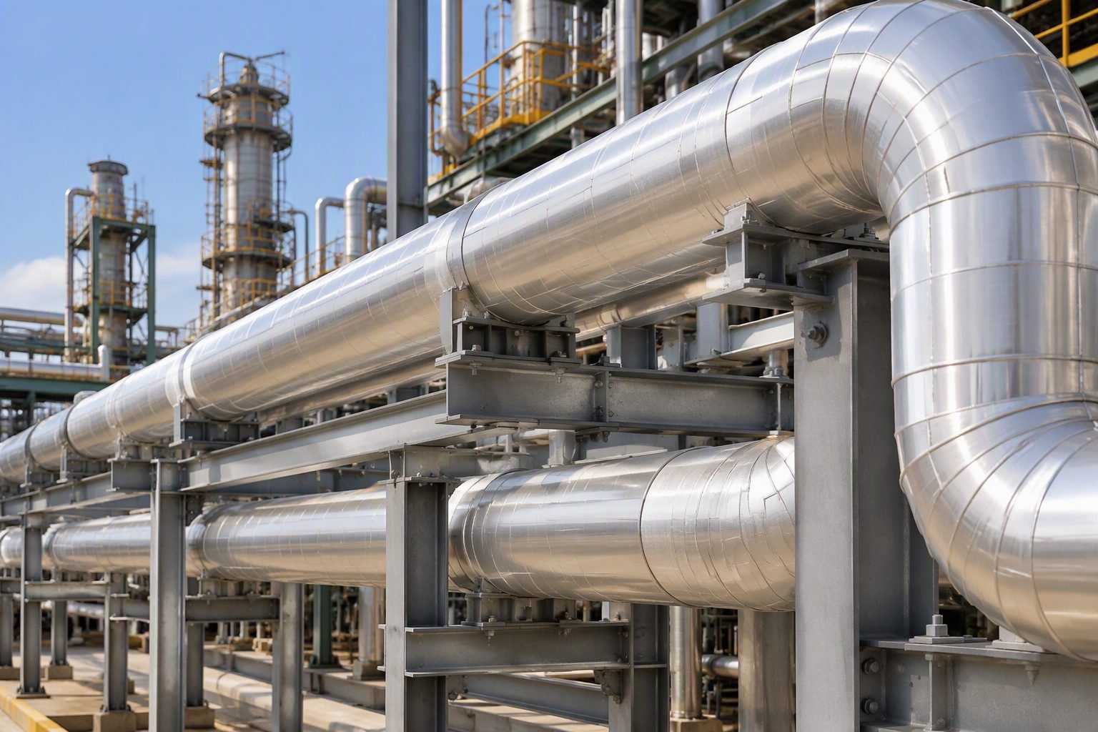
Calculating Support Span for Insulated Lines in Process Plants
Insulation span limits define the maximum allowable distance between pipe supports when accounting for the combined dead weight of the carrier pipe, contained fluid, and exterior cladding systems per ASME B31.3 criteria.
In my two decades of reviewing pipe rack designs across mega-refineries and chemical processing units, I frequently observe junior engineers applying bare-pipe span tables directly to heavily insulated lines. This oversight ignores the massive compounding dead load introduced by calcium silicate, cellular glass, and aluminum cladding. When thermal insulation and weather jacketing are neglected in structural span calculations, mid-span sag exceeds allowable limits, inducing severe bending moments and localized shell stresses at support shoe interfaces.
Mastering support span for insulated lines requires an integrated approach combining fluid density, insulation volumetric mass, structural bending stress, and maximum permissible beam deflection. Throughout this guide, I will walk you through the rigorous analytical steps necessary to keep your piping systems compliant, safe, and durable under extreme operational conditions.
Key Engineering Takeaways
- Insulation and cladding can increase total distributed pipe weight by up to 200 percent on small-bore lines.
- B31.3 allowable bending stresses govern support spacing alongside standard 2.5 mm vertical deflection limits.
- Support shoe selection must prevent crushing of soft insulation materials while maintaining thermal efficiency.
Support Span Calculation Methodology for Insulated Piping
Support span engineering involves solving beam mechanics equations for continuous or simply supported pipes subjected to uniform distributed dead loads, internal pressures, and thermal expansion forces.
When calculating the maximum allowable span for an insulated process line, the total distributed load (W_total) is the summation of the empty pipe weight (W_pipe), the internal fluid weight (W_fluid), the insulation material weight (W_ins), and the exterior cladding weight (W_clad). Failing to sum these components accurately leads to premature support failure or overstressed piping geometry.
The fundamental bending stress equation derived from ASME Boiler and Pressure Vessel Code Section VIII and ASME B31.3 sets the maximum longitudinal bending stress (S_b) equal to the bending moment (M) divided by the section modulus (Z). For a simply supported uniform beam subjected to a distributed load, the maximum moment occurs at mid-span.
Fundamental Distributed Load Formula:
W_total = W_pipe + W_fluid + W_ins + W_clad
Maximum Bending Moment (Simply Supported):
M = (W_total * L^2) / 8
Maximum Bending Stress Criterion:
Sb = M / Z <= 0.75 * Sh
Accounting for Insulation and Cladding Mass
Insulation thickness varies depending on thermal design requirements, operating temperatures, and personnel protection standards (typically governed by ASTM C585 and ASTM C680). To determine W_ins, you must calculate the cross-sectional volume of the annular insulation ring per unit length, multiplied by the material density.
Similarly, exterior weather jacketing—commonly aluminum or stainless steel per ASTM B209—adds significant circumferential weight. In small-diameter lines (e.g., 2-inch and 3-inch NPS), the insulation and cladding can outweigh the steel pipe itself by a factor of two or three. Ignoring this reality causes actual mid-span deflections to blow past the standard 2.5 mm or span/360 deflection thresholds.
Critical Design Warning: Small-Bore Insulation Overload
Never rely on standard bare-pipe span charts for lines under 4 inches NPS that require thick cryogenic or high-temperature refractory insulation. The combined dead load radically shortens the maximum safe span, requiring intermediate supports or structural stiffeners to prevent excessive sagging and flange leakage.
Deflection and Stress Limitations in Pipe Racks
Pipe span limits are rarely dictated by stress alone; deflection criteria often govern the calculation. Excessive vertical sag creates pockets in sloped drain lines, imposes unintended bending loads on branch connections, and causes misalignment at rotating equipment nozzles. Per standard industrial practices, total vertical deflection (y) under operating load should not exceed 25 mm or the specific span-to-360 ratio, whichever is more stringent.
Furthermore, engineers must evaluate thermal expansion interactions. When an insulated carbon steel or alloy pipe expands axially, friction at the pipe support sliding plate creates axial forces that combine with gravity bending stresses. Using pipe stress analysis software like Hexagon CAESAR II is essential to verify that combined stress intensities remain within Code allowable limits throughout all operational cycles.
Span optimization trade-offs balance structural material costs against the rigorous analytical overhead required to accurately model insulated piping systems.
Advantages
- Prevents localized pipe shell distortion and crushing at support shoe interfaces.
- Ensures full compliance with ASME B31.3 longitudinal stress and bending limits.
- Eliminates liquid pooling and draining issues caused by excessive mid-span pipe sag.
- Reduces long-term maintenance costs by preventing insulation jacket cracking and water ingress.
- Optimizes structural steel rack utilization by avoiding overly conservative or overly aggressive span guesses.
Disadvantages
- Requires tedious, time-intensive calculations to compute accurate insulation and cladding mass distributions.
- Demands frequent support locations, increasing total structural steel fabrication and erection costs.
- Complicates field constructability due to tighter tolerances on support bracket placement.
- Requires specialized support accessories like shoes, wear pads, and cradles to protect the insulation system.
- Increases engineering man-hours needed for detailed pipe stress modeling in software like Hexagon CAESAR II.
Industrial deployment environments require rigorous application of insulated support span criteria across high-temperature refining, cryogenic processing, and steam distribution networks.
High-Temperature Refinery Transfer Lines
Hydrocracker and fluid catalytic cracking units transport heavy gas oils and hydrocarbon vapors at temperatures exceeding 400 degrees Celsius. These lines feature thick refractory or mineral wool insulation encased in heavy aluminum cladding, necessitating shortened pipe support spans to prevent high-temperature creep and excessive bending sag between pipe rack bents.
Cryogenic LNG Liquefaction Piping
Liquefied natural gas facilities operate at extreme sub-zero temperatures, requiring multilayer cellular glass or polyurethane foam insulation paired with vapor-sealed stainless steel jacketing. Accurate support span calculations are critical here to accommodate specialized cryogenic support shoes and prevent localized thermal contraction stresses from fracturing the insulation barrier.
Offshore Platform Utility Steam Headers
Topside process modules on floating production storage and offloading vessels experience severe environmental wave motions alongside high-pressure steam distribution loads. Insulated steam lines on offshore pipe racks must incorporate rigorous span limitations and clamp designs to withstand combined dead weight, thermal growth, and dynamic structural acceleration forces.
Chemical Plant Acid and Caustic Transfer Headers
Corrosive chemical transport headers often require heat tracing combined with thick thermal insulation and heavy fiberglass-reinforced plastic or stainless cladding. Engineers must recalculate maximum support spacing to account for the heavy assembly weight, ensuring that localized support brackets do not compress the tracing elements or damage the carrier pipe wall.
Support Span Reference Data for Insulated Process Lines
Calculating the maximum allowable support span for insulated piping systems requires rigorous integration of total dead weight, fluid service density, thermal expansion forces, and allowable bending stress limits outlined in ASME B31.3 Process Piping. When thermal insulation and weatherproofing cladding are added to a steel pipe, the distributed load per unit length increases substantially. This additional mass directly accelerates downward dead weight deflection, raising longitudinal bending stresses at mid-span and altering the fundamental natural frequency of the piping span. Piping engineers must evaluate these combined dead loads alongside operating pressures and transient dynamic loads to prevent premature sag, flange leakage, or localized shell buckling at support shoe contact points.
The following engineering reference table outlines typical maximum uninhibited span limits for standard carbon steel process pipes operating at ambient temperature under water service, contrasted against insulated configurations featuring high-density calcium silicate and aluminum jacketing. These figures illustrate how thermal lagging reduces allowable support spacing to maintain beam deflection within the standard code threshold of 25 millimeters or half the nominal pipe diameter, whichever is more restrictive. Review these values carefully when establishing initial routing layouts on heavy industrial pipe racks.
| Nominal Pipe Size (NPS) | Schedule / Wall | Bare Pipe Span Limit (m) | Insulated Span Limit (m) | Governing Criteria |
|---|---|---|---|---|
| 2 Inch | Sch 40 | 3.05 m | 2.45 m | Deflection Limit (< 25 mm) |
| 4 Inch | Sch 40 | 4.27 m | 3.50 m | Bending Stress (ASME B31.3) |
| 6 Inch | Sch 40 | 5.18 m | 4.20 m | Bending Stress (ASME B31.3) |
| 8 Inch | Sch 40 | 5.79 m | 4.80 m | Combined Dead Weight Load |
| 12 Inch | Standard | 6.71 m | 5.60 m | Deflection Limit (< 25 mm) |
| 16 Inch | Standard | 7.62 m | 6.35 m | Bending Stress (ASME B31.3) |
Note: Values assume continuous beam configurations operating under standard hydrostatic test conditions with 50mm calcium silicate insulation and 0.6mm aluminum jacketing. Always cross-check spans against localized concentrated valve weights.
Technical Mapping & Specifications Matrix
Modern piping engineering relies on a standardized network of governing bodies, mathematical models, material specifications, and software analysis frameworks to ensure structural integrity across extreme operating environments. When designing support arrangements for insulated lines, engineers must correlate mechanical properties defined in international codes with practical software inputs. This multi-discipline synchronization prevents catastrophic failures resulting from unmitigated sag, excessive shear stresses at pipe shoes, or localized crushing of thermal insulation layers under high-load clamp assemblies.
The following entity matrix maps out the critical engineering parameters, governing standards, structural acronyms, and analytical tools utilized daily in advanced piping stress analysis. Each entity represents a vital pillar in maintaining code compliance under ASME Boiler and Pressure Vessel Code and related standards. Reference this matrix during interdisciplinary design reviews to maintain complete traceability across mechanical, structural, and thermal insulation specifications.
| Entity / Acronym | Classification | Governing Standard | Engineering Application |
|---|---|---|---|
| ASME B31.3 | Design Code | ASME | Process piping design, allowable stress limits, and support span formulas. |
| MSS SP-58 | Hardware Standard | MSS | Materials, design, manufacture, and selection of pipe hangers and supports. |
| ASTM A53 / A106 | Material Spec | ASTM | Standard specifications for seamless and welded carbon steel process piping. |
| CAESAR II | Analysis Software | Hexagon MI | Computerized stress analysis modeling dead weight, thermal, and wind loads. |
| Calcium Silicate | Thermal Insulation | ASTM C533 | High-temperature rigid insulation adding significant distributed dead load. |
| Pipe Shoe / Saddle | Support Hardware | MSS SP-69 | Elevates insulated lines above structural steel, preventing jacket crushing. |
Integration Tip: Ensure that software weight multipliers in CAESAR II accurately account for specific insulation dry density plus expected moisture absorption allowances in humid outdoor process units.
Site Verification Checklist for Insulated Pipe Spans
Validating maximum support span calculations requires rigorous field verification before mechanical completion and hydrotesting. In my field experience, discrepancies between isometric drawings and actual erected pipe rack geometry frequently lead to over-spanned lines, excessive sag, and localized overstressing at support interfaces. Engineers must systematically verify that insulation thickness, cladding density, shoe attachments, and structural steel elevations match design assumptions.
Perform a comprehensive site audit using the structured verification framework below to ensure complete compliance with ASME B31.3 and MSS SP-58 standards before introducing process fluids or initiating thermal commissioning cycles.
Field Inspection & Verification Checkpoints
- Insulation Density Verification: Confirm installed thermal insulation material density matches engineering calculation sheets (e.g., 240 kg/m3 for calcium silicate).
- Cladding Thickness Audit: Measure aluminum or stainless steel weatherproofing jacketing gauge to verify dead weight load aligns with design assumptions.
- Support Span Measurement: Tape measure verify actual distance between adjacent support centerlines against maximum allowable span limits.
- Pipe Shoe Elevation Check: Ensure all insulated lines utilize appropriately sized pipe shoes or saddles to maintain clearance above structural steel.
- Vapor Barrier Integrity: Inspect insulation vapor stops and sealant applications near support attachments to prevent moisture ingress and corrosion under insulation.
- Secondary Steel Alignment: Verify rack secondary steel members are level, properly welded, and free from excessive deflection before piping placement.
- Concentrated Load Review: Check that valves, inline instruments, and flanges near mid-span have dedicated secondary supports or reduced spans.
- Thermal Movement Clearance: Ensure guide and anchor placements permit uninhibited axial and lateral expansion during high-temperature operation.
Document all verified inspection items in the permanent quality assurance turnover dossier. Any deviation exceeding five percent from calculated maximum span limits requires formal engineering re-evaluation and stress re-analysis.
Field Case Study: Real-World Application
A critical mid-stream refinery expansion project experienced severe sagging and localized insulation crushing on a major 10-inch hot oil transfer line routed across an outdoor pipe rack. The piping system, designed for 350 degrees Celsius service, utilized heavy calcium silicate insulation with aluminum jacketing but was erected using standard bare pipe support spans found in general company piping standards. Within six months of commissioning, operators observed excessive mid-span deflection and moisture ingress through buckled weatherproofing jacketing near support locations.
Identified Engineering Problems
The root cause analysis revealed multiple severe design and installation oversights that compromised structural integrity:
- Support spans were engineered using bare carbon steel weight formulas without factoring in the 38 percent mass increase contributed by the thick calcium silicate insulation and aluminum cladding.
- Standard U-bolt clamps were installed directly over the insulated aluminum jacketing without load-distributing pipe shoes or saddles, crushing the insulation layers.
- Hydrostatic testing was performed with temporary supports that failed to mimic operational support spacing, causing permanent plastic deformation during water filling.
- Thermal expansion forces were constrained by improper guide positioning, superimposing high axial compressive stresses onto already overloaded bending moments.
Corrective Actions & Measurable Outcomes
To resolve the failure and prevent future containment loss, a comprehensive engineering remediation program was executed:
- Re-analyzed the entire piping network in Hexagon CAESAR II incorporating accurate distributed insulation dead loads and thermal expansion profiles.
- Reduced maximum support spans by 22 percent, installing intermediate structural steel support bents along the pipe rack.
- Replaced crushed clamping arrangements with welded-in-place structural steel pipe shoes featuring load-distributing base plates.
- Achieved complete compliance with ASME B31.3 stress ratios, reducing maximum combined bending stress from 94 percent to 62 percent of allowable limits.
Engineering Recommendation: Always mandate rigorous multi-variable dead weight calculations that explicitly integrate thermal insulation, cladding, and fluid service density during the preliminary routing phase of any heavy industrial piping project.
Frequently Asked Engineering Questions
How does mineral wool insulation weight alter the maximum support span calculations for carbon steel lines?
- Total distributed load (W_total) increases linearly with insulation thickness and density.
- Maximum bending moment scales with the square of the span, necessitating shorter spans to maintain compliance with ASME stress limits.
- Deflection checks under operating weight must remain below 1/360th of the span or 25 mm to prevent insulation crushing at support shoes.
What is the primary code limitation for allowable bending stress in insulated process piping spans?
- Longitudinal stress from internal pressure and dead weight must not exceed the basic allowable stress at operating temperature (S_h).
- Bending stress is calculated using the elastic section modulus of the corroded pipe cross-section.
- Support spans must be shortened if longitudinal stress values exceed 0.8 times the yield strength of the pipe material.
How do insulation shields prevent localized crushing at pipe support shoes on long spans?
- Insulation inserts (like calcium silicate or high-density polyurethane foam) transfer the heavy vertical reaction forces directly to the pipe wall.
- Half-round saddle plates distribute the concentrated point load across a wider arc on the pipe exterior.
- Corrosion under insulation (CUI) risks are mitigated by sealing the shoe assembly with appropriate mastic and flashing.
Why must wind and seismic lateral loads be evaluated alongside vertical dead weight in outdoor pipe racks?
- Cladding outer diameter dictates the wind drag coefficient and total lateral force per linear foot according to ASCE 7 standards.
- Combined axial, bending, and shear stresses must be evaluated using interaction equations under combined loading categories.
- Seismic base shear calculations must factor in the heavy mass of saturated insulation materials in humid process environments.
What software tools and calculation methods do piping engineers use for complex insulated span layouts?
- CAESAR II and AutoPIPE are industry-standard packages for verifying code compliance against ASME B31.3 requirements.
- Spreadsheet tools incorporating formulas from MSS SP-58 provide rapid screening for standard pipe rack spacing.
- Thermal expansion anchor movements must be reconciled with intermediate guide and support placement to prevent binding.
Field Recommendation
- If you are routing large-diameter steam lines with multi-layer calcium silicate insulation through an outdoor rack, always calculate spans based on the wet insulation density rather than dry catalog ratings to prevent unexpected mid-span sag after heavy rainfall.
- When brownfield tie-ins require adding thick cryogenic insulation to existing brownfield pipe racks, do not rely on original uninsulated span tables; immediately verify that steel bracket load capacities and allowable pipe deflections will not be violated under the new distributed weight.
- Specify bolted clamp-type insulation protection shields whenever span lengths exceed 6 meters to ensure that concentrated shear stresses at support shoes do not deform thin-walled pipe geometries or damage vapor barriers.
- Always coordinate pipe stress analysis models with structural engineering teams before freezing rack steel layouts, ensuring that combined thermal growth and heavy insulated dead loads are fully transferred into primary support columns without overstressing intermediate steel members.
Complete Course on
Piping Engineering
Check Now
Key Features
- 125+ Hours Content
- 500+ Recorded Lectures
- 20+ Years Exp.
- Lifetime Access
Coverage
- Codes & Standards
- Layouts & Design
- Material Eng.
- Stress Analysis
