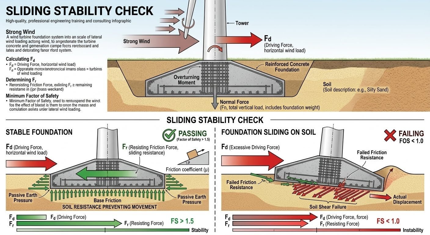
Sliding Stability Check for Industrial Foundations Under Extreme Wind Loads
In my two decades of executing piping and structural engineering design for major hydrocarbon processing facilities, few failure modes are as insidious as lateral base sliding. When a severe squall or hurricane strikes an unseated vertical vessel, flare stack, or long pipe rack, the resulting horizontal wind drag forces test the absolute shear capacity of the underlying soil interface. Without performing an exhaustive sliding stability check early in the civil design phase, expensive deep foundation retrofits or catastrophic tilting events frequently plague plant commissioning.
Evaluating this mechanical equilibrium requires synthesizing structural overturning moments, dead load downward stabilizations, and complex soil mechanics parameters. Throughout this guide, I examine the exact formulations, safety margins, and governing building codes required to keep your heavy industrial foundations anchored securely to the earth.
Key Engineering Takeaways
- Driving forces are derived from extreme lateral wind pressures multiplied by projected structural surface areas.
- Resisting forces combine concrete-to-soil friction and toe passive soil resistance, factored by established safety margins.
- ASCE 7 and ACI 318 mandate minimum safety factors against lateral sliding, typically set at 1.5 under normal operating conditions.
- Groundwater table fluctuations severely reduce effective vertical loads and must be incorporated into net buoyancy calculations.
Structural Mechanics of the Sliding Stability Check
When analyzing massive industrial structures, the sliding stability check acts as the primary defense against horizontal displacement. The driving force (F_d) originates predominantly from wind pressures acting on elevated piping, insulation, structural framing, and equipment shells. According to ASCE 7 Minimum Design Loads and Associated Criteria for Buildings and Other Structures, wind velocity pressures are converted into lateral forces via exposure coefficients, topographic factors, and gust effect multipliers.
To resist this lateral surge, the foundation relies on two distinct physical mechanisms at the soil interface: base sliding friction and passive earth pressure. Base friction is a direct function of the effective vertical dead load acting downward on the foundation base, combined with the coefficient of friction between the concrete underside and the subgrade soil or mud mat. Passive earth pressure, conversely, represents the lateral resistance mobilized when the vertical edge of the foundation pushes against the adjacent compacted backfill soil.
Governing Mathematical Formulation
The fundamental factor of safety against sliding (FS_sliding) is expressed through the following engineering equation:
FS_sliding = (Fr + Pp) / Fd >= 1.5
- Fr = Total resisting frictional force at foundation base (N or lb)
- Pp = Allowable passive earth pressure resisting lateral movement (N or lb)
- Fd = Total lateral driving wind load (N or lb)
Calculating the base frictional resistance (Fr) requires careful evaluation of buoyancy effects caused by high water tables. If the groundwater level rises above the bottom of the footing, hydrostatic uplift reduces the effective net weight of the concrete and equipment package. Consequently, the normal force driving friction drops precipitously. In my design reviews, I always verify whether geotechnical reports account for seasonal high water tables, as neglecting buoyancy is a leading cause of foundation failure.
Furthermore, the friction coefficient (μ) between concrete and soil is strictly governed by geotechnical parameters. For poured-in-place concrete resting directly on a lean concrete mud mat, μ typically ranges between 0.35 and 0.40. When resting on compacted granular gravel subgrades, μ can increase up to 0.55. Cohesive clay subgrades, however, present severe sliding risks because their undrained shear strength can degrade rapidly under cyclic wind loading and moisture ingress.
Critical Engineering Warning: Passive Pressure Reliability
While passive earth pressure (Pp) significantly boosts lateral resistance, ACI 318 Building Code Requirements for Structural Concrete warns against relying entirely on passive pressure if adjacent soil can be excavated, eroded, or removed during future plant maintenance operations. Standard engineering practice dictates ignoring passive pressure unless permanent, unalterable paving or unexcavated grade surrounds the foundation perimeter.
When wind loads create high overturning moments alongside lateral drag, the resultant load vector shifts toward the edge of the footing. This eccentric loading creates a trapezoidal or triangular contact pressure distribution beneath the base. Where the resultant force falls within the middle third (kern) of the foundation, the entire base remains in compression. If eccentricity exceeds the kern, partial uplifting occurs, reducing the effective frictional area and accelerating sliding vulnerability.
To mitigate inadequate sliding resistance without unnecessarily enlarging massive concrete footprints, engineers deploy several specialized geometrical enhancements. Shear keys—reinforced concrete lugs extending downward from the bottom of the footing into competent subgrade—are exceptionally effective. A shear key forces the failure plane deeper into the soil mass, mobilizing deep soil shear strength rather than relying solely on superficial concrete-soil sliding friction.
Advantages of Rigorous Sliding Checks
- Regulatory Compliance: Ensures full alignment with ASCE 7 and ACI 318 safety margins, passing strict third-party engineering audits.
- Structural Integrity: Prevents catastrophic lateral shifting of interconnected high-temperature piping networks and vessels.
- Optimized Sizing: Avoids blindly over-designing massive concrete footprints by accurately factoring beneficial base friction.
- Proactive Mitigation: Identifies problematic soft soil strata early, allowing cost-effective shear key integration before construction.
- Buoyancy Awareness: Accounts for fluctuating groundwater tables, averting unexpected loss of frictional resistance.
Disadvantages & Design Limitations
- Geotechnical Dependency: Relies heavily on accurate soil shear parameters that can vary widely across large industrial sites.
- Excavation Vulnerability: Passive earth pressure benefits can be compromised if future plant modifications require trenching nearby.
- Construction Complexity: Adding concrete shear keys increases formwork difficulty and excavation depths during civil execution.
- Wind Load Uncertainty: Extreme meteorological events can exceed historical design return periods, straining safety margins.
- Settlement Tradeoffs: Increasing dead weight to boost friction can exacerbate long-term consolidation settlement in soft clay deposits.
1. Tall Industrial Flare Stacks and Exhaust Towers
Slender cantilevered structures like flare stacks and exhaust chimneys experience immense overturning moments and lateral wind drag. Because their footprint is relatively narrow compared to their total height, base sliding and overturning are the governing failure modes. Performing a strict sliding stability check ensures the octagonal or circular concrete mat remains perfectly anchored without lateral displacement during hurricane-force gusts.
2. Heavy Petrochemical Fractionation Columns
Massive distillation columns in refineries feature large surface areas exposed to wind, compounded by connected large-diameter piping loops. Under extreme wind storms, the combined horizontal shear stress at the base of the pedestal requires extensive ballast weight or deep foundation shear keys. Civil engineers utilize sliding verification models to balance vessel operating weights against peak wind shear.
3. Long-Span Pipe Racks in Coastal Facilities
Multi-tier pipe racks spanning across process units carry dense bundles of pressurized hydrocarbon lines. Coastal installations face aggressive wind profiles combined with saturated, low-friction subsoils. Evaluating lateral sliding stability across multiple interconnected footing pads prevents differential lateral movement that could overstress rigid piping branches and cause flange leakage.
4. Air Cooler Banks and Fin-Fan Structures
Elevated air-cooled heat exchangers present wide, box-like obstruction surfaces to high-velocity crosswinds. Their relatively low operating dead weight offers limited vertical stabilizing force against wind drag. Structural designers frequently integrate concrete grade beams and deep anchor tie-ins to satisfy the required 1.5 safety factor against lateral sliding.
5. Large Atmospheric Storage Tank Foundations
Empty or partially filled field-erected storage tanks subjected to high winds are notoriously susceptible to sliding and shell buckling. While ringwall and slab foundations provide substantial dead weight, empty tank conditions eliminate liquid ballast. Rigorous stability checks dictate minimum anchor bolt requirements and ringwall embedment depths to resist sliding shear.
Sliding Stability Calculation Parameters and Load Factors
Executing a robust sliding stability check requires meticulous quantification of lateral driving forces and resisting mechanisms. In my piping engineering practice, I rely on standardized design parameters derived from ASCE 7 and ACI 318 guidelines to evaluate wind-induced base shear. The following engineering data table outlines the core variables, typical values, and governing code references utilized when modeling foundation sliding mechanics on treated soil subgrades.
Every parameter directly influences the final factor of safety equation, where driving forces from wind exposure must be counteracted by factored base friction and passive earth pressure resistance along the foundation toe.
| Parameter Name | Symbol | Typical Value / Range | Governing Code | Engineering Application |
|---|---|---|---|---|
| Lateral Wind Force | Fd | 15 kN to 120 kN | ASCE 7-22 | Total horizontal shear load transferred from structural steel and pipe racks to the foundation top. |
| Base Friction Factor | tan(delta) | 0.30 to 0.55 | ASTM D3080 | Coefficient of friction between the concrete foundation base and underlying compacted granular soil. |
| Passive Earth Pressure | Pp | 10 kN/m to 85 kN/m | ASTM D6528 | Resisting lateral soil pressure mobilized against the embedded vertical face of the footing. |
| Effective Vertical Load | W_eff | 50 kN to 500 kN | ACI 318-19 | Total dead weight of concrete foundation and superimposed permanent equipment minus buoyancy. |
| Factor of Safety | FS | >= 1.50 (Wind) | OSHA / ACI | Minimum allowable ratio of total resisting forces to total lateral driving shear forces. |
Note: Passive earth pressure contributions should be discounted by 50% unless continuous compaction testing guarantees undisturbed native backfill directly adjacent to the foundation wall.
Technical Mapping & Specifications Matrix
Navigating industrial structural engineering projects demands clear traceability of analytical models, material classifications, and regulatory benchmarks. The matrix below aggregates critical engineering entities associated with lateral wind load dissipation and soil-structure interaction.
By standardizing these entities across multidisciplinary design deliverables, piping and civil teams eliminate conflicting assumptions regarding foundation sliding resistance.
| Entity Classification | Structural Acronym | Primary Physical Parameter | Reference Standard | Design Threshold |
|---|---|---|---|---|
| Lateral Load Transfer | LLT-01 | Wind Shear (Fd) | ASCE 7 | Must not exceed 65% of base friction without shear keys. |
| Geotechnical Interface | GTI-02 | Interface Friction (tan delta) | ASTM D5321 | Minimum 0.35 for poured concrete on crushed stone. |
| Passive Resistance | PR-03 | Rankine Passive Pressure (Kp) | ASTM D2487 | Full mobilization requires 1.5% to 2.0% foundation movement. |
| Concrete Integrity | CI-04 | Compressive Strength (fc) | ACI 318 | Minimum 28-day cylinder strength of 30 MPa. |
| Stability Index | SI-05 | Factor of Safety (FS) | ASME BPVC | FS >= 1.5 under extreme service load combinations. |
Reference standard compliance must be verified against local municipal building codes and site-specific geotechnical investigation reports prior to final anchor bolt and footing construction release.
Site Verification Checklist for Foundation Sliding Stability
Ensuring absolute structural security against lateral wind shear requires a rigorous site inspection protocol. In my engineering audits, I enforce this systematic verification checklist before signing off on foundation backfilling and equipment installation.
Each verification item bridges theoretical calculation models with physical construction realities, ensuring no hidden geotechnical vulnerabilities compromise the safety factor.
Mandatory Sliding Stability Inspection Checkpoints
- 1 Subgrade Compaction Verification: Confirm that the native or engineered fill beneath the footing base achieves a minimum of 95 percent Modified Proctor density in accordance with ASTM D1557.
- 2 Interface Cleanliness Inspection: Ensure the bottom of the concrete formwork is entirely free of mud, debris, and loose organic matter prior to concrete placement to guarantee unimpeded concrete-to-soil friction.
- 3 Passive Backfill Compaction: Verify that soil adjacent to the foundation perimeter is placed in 200 mm lifts and compacted to strict geotechnical specifications to properly mobilize passive earth pressure (P_p).
- 4 Drainage System Integrity: Inspect perimeter drainage layers to prevent hydrostatic pore pressure buildup beneath the base slab, which would otherwise reduce effective vertical weight and trigger sliding failure.
- 5 Anchor Bolt and Shear Key Alignment: Check that embedded shear keys and anchor assemblies match structural fabrication drawings exactly, adhering to AISC and ACI 318 tolerances.
Validation Rule: Any deviation from specified backfill compaction or drainage parameters invalidates the baseline sliding stability calculation and requires an immediate engineering re-evaluation.
Field Case Study: Real-World Application
During the expansion of a coastal petrochemical processing plant in a hurricane-prone zone, our engineering team evaluated a sprawling pipe rack foundation subjected to extreme lateral wind gusts exceeding 180 kilometers per hour. Initial site assessments indicated alarming lateral displacement tendencies during severe storm simulations.
The Sliding Stability Problem
An excessive lateral wind load overwhelmed the baseline friction resistance of the shallow mat foundation, driving the calculated factor of safety down to a dangerous 0.85 and triggering localized soil shear failure.
- High surface area of large-diameter insulated piping exposed to intense coastal wind vectors.
- Inadequate native soil friction coefficient (tan delta equal to 0.28) over saturated clay strata.
- Absence of perimeter passive earth pressure support due to uncompleted trench backfilling.
- Reduction of effective vertical dead load caused by temporary empty operating conditions in parallel headers.
The Engineering Outcome
By implementing targeted structural and geotechnical remediation measures, we successfully restored lateral stability and increased the operational safety factor above the mandatory 1.50 threshold.
- Installed reinforced concrete toe shear keys extending 600 mm into stiff native bearing strata.
- Replaced sub-base material with compacted crushed limestone aggregate, increasing friction to 0.48.
- Enforced strict compaction protocols for perimeter backfill to fully mobilize passive soil pressure.
- Achieved a final verified sliding safety factor of 1.72 under extreme ASCE 7 load combinations.
Recommendation: For coastal industrial installations, always integrate concrete shear keys into shallow foundation designs when site soil friction values fall below standard thresholds.
