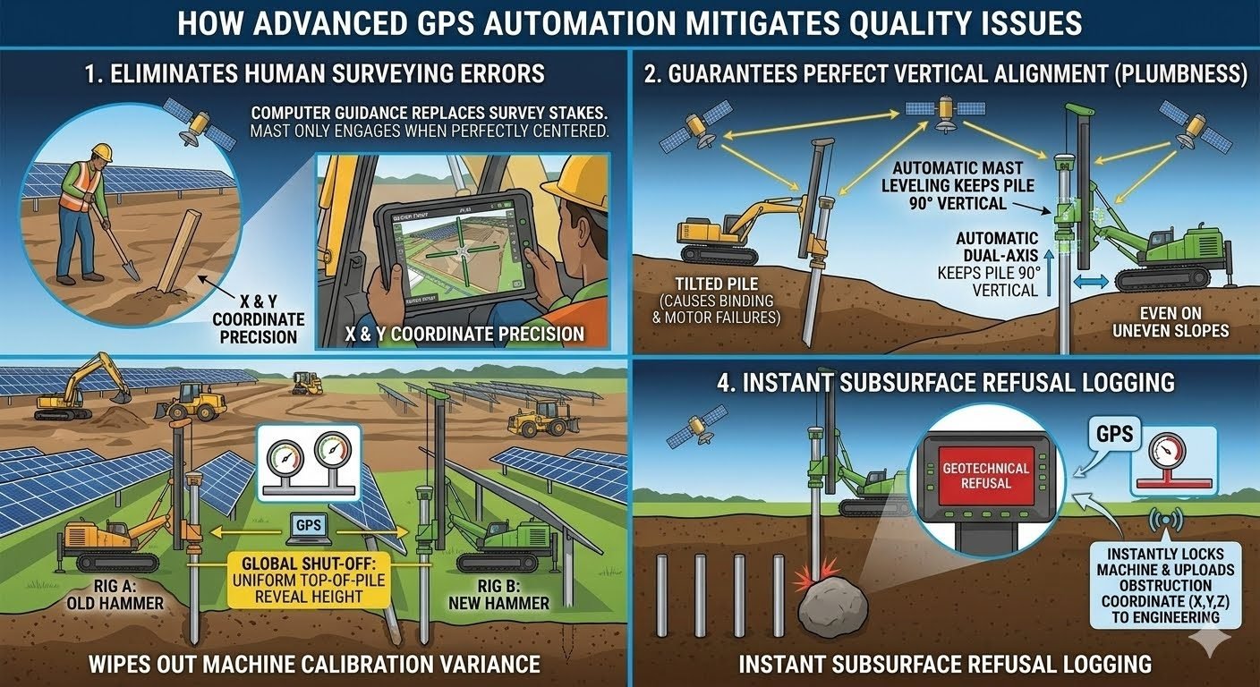
How GPS Pile Installation Eliminates 4 Field Errors
In my 20 years of managing heavy civil and utility-scale solar projects, I have watched traditional surveying methods fail repeatedly on the flat, featureless expanses of modern job sites. A single misplaced wooden stake or a tired surveyor can throw off an entire row of tracker foundations, leading to catastrophic binding downstream. By transitioning to automated GPS pile installation, we remove human error from the layout phase entirely, ensuring that the rig only drives when the mast is perfectly centered.
Key Takeaways
- Eliminates manual survey stakes and human positioning errors entirely.
- Maintains strict vertical plumbness to prevent downstream tracker binding.
- Standardizes reveal heights across mixed equipment fleets using global shut-off signals.
- Logs subsurface refusal coordinates instantly for immediate engineering review.
Why GPS Pile Installation Prevents Structural Failures
1. Eliminating Human Surveying Errors
Traditional piling relies on physical stakes driven into the soil by a survey crew. These stakes are easily knocked over by heavy machinery, washed away by rain, or misread by the rig operator. In my experience, a surveyor working in dusty, high-wind conditions can easily misplace a stake by several inches, which is unacceptable for modern structural tolerances.
Automated systems replace physical stakes with a digital design file loaded directly into the rig’s onboard computer. The system uses Real-Time Kinematic (RTK) GPS to achieve sub-centimeter horizontal accuracy. The hydraulic mast will not engage or allow the hammer to strike until the tool center point is perfectly aligned with the digital design coordinates. This hard interlock prevents the operator from driving a pile in the wrong location.
2. Perfect Vertical Alignment (Plumbness)
A pile that is driven out of plumb introduces eccentric loading into the foundation, which reduces its load-bearing capacity. For solar tracker projects, even a minor tilt can cause the torque tubes to bind, leading to motor failures and structural fatigue. Traditional methods rely on the operator looking at a manual bubble level mounted on the mast, which is highly subjective and prone to parallax error.
To calculate the horizontal deviation at the top of a pile, we use the formula: Delta equals L multiplied by the sine of the tilt angle theta, where L is the exposed pile height. For an exposed height of 2500 millimeters and a tilt angle of 0.85 degrees, the horizontal deviation is approximately 37 millimeters. If the tilt increases to 3.0 degrees due to manual alignment errors, the deviation jumps to 131 millimeters, which exceeds structural tolerances.
Automated dual-axis mast leveling continuously monitors the angle of the lead system using high-speed inclinometers. The system automatically adjusts the hydraulic positioning cylinders to maintain a true 90-degree vertical angle. This correction occurs in real-time as the pile is driven, compensating for uneven ground slopes and soil resistance that would otherwise push the pile off-course.
3. Wiping Out Machine Calibration Variance
On large construction sites, you will often find a mix of old and new piling rigs working side-by-side. Rig A might have an older hydraulic hammer with worn seals, while Rig B features a brand-new, high-frequency hammer. If these machines drive piles based on manual depth marks or blow counts, the resulting reveal heights will vary wildly across the site.
GPS automation solves this by establishing a global shut-off signal linked to the digital elevation model. The system continuously tracks the absolute Z-coordinate of the pile head. Once the pile reaches the exact design elevation, the system cuts power to the hammer automatically. This ensures a uniform top-of-pile reveal height across the entire fleet, regardless of individual machine wear or operator experience.
How GPS Pile Installation Controls Geotechnical Refusal
When a pile hits an unexpected underground obstruction, such as a large boulder or a dense limestone layer, it reaches geotechnical refusal. In traditional operations, the operator must stop, write down the pile number on a paper log, and notify the engineering team. This manual process is slow, prone to transcription errors, and often results in lost data that delays remediation.
With GPS automation, the moment the penetration rate drops below the programmed threshold (for example, less than 10 millimeters over 10 consecutive blows), the system flags a refusal event. It instantly locks the exact X, Y, and Z coordinates of the pile tip and uploads this data to the cloud. The engineering team can view the refusal map in real-time, allowing them to approve pre-drilling or design a shorter pile modification without stopping the field crew.
Advantages
- Eliminates manual staking costs and surveyor scheduling bottlenecks.
- Achieves sub-centimeter horizontal and vertical accuracy across thousands of foundations.
- Generates real-time digital twin data for immediate quality control and as-built reporting.
- Reduces structural risk of tracker binding and motor failures on solar projects.
- Identifies and maps underground obstructions instantly to speed up engineering remediation.
Disadvantages
- Requires high initial capital investment for RTK-GPS hardware and software licensing.
- Vulnerable to satellite signal loss in deep valleys or near dense forest canopies.
- Demands specialized operator training and on-site technical support for system calibration.
- Depends heavily on the accuracy of the initial digital design files and coordinate systems.
In my two decades of field experience, I have observed that manual pile driving often suffers from cumulative error propagation. When operators rely on physical stakes and visual plumb-bobs, the variance in pile reveal height and verticality can exceed 50mm, leading to significant structural rework during tracker installation. The following table outlines the transition from traditional manual tolerances to the precision afforded by GPS-integrated machine control systems.
These values represent the shift from subjective operator judgment to machine-enforced digital constraints. By utilizing ASME-compliant structural benchmarks, we ensure that the pile foundation remains within the elastic limits required for long-term solar array stability.
| Parameter | Manual Method | GPS Automated |
|---|---|---|
| X-Y Positioning | +/- 50mm | +/- 10mm |
| Verticality (Plumb) | +/- 2.0 Degrees | +/- 0.2 Degrees |
| Reveal Height | +/- 30mm | +/- 5mm |
The integration of GPS automation into pile driving rigs requires a sophisticated handshake between satellite positioning data and hydraulic control logic. This matrix maps the core technical entities that govern the installation process, ensuring that every pile is driven to the exact geotechnical requirements specified in the project design documents.
By standardizing these inputs, we eliminate the “black box” nature of traditional pile driving. Each entity listed below acts as a critical node in the API-aligned quality assurance workflow, providing a digital audit trail for every single pile installed on the site.
| Entity | Function | Standard Reference |
|---|---|---|
| GNSS Receiver | Real-time coordinate acquisition | ISO 19157 |
| Dual-Axis Inclinometer | Mast plumbness verification | ASTM D1143 |
| Hydraulic Cut-off | Reveal height enforcement | ASME B30.5 |
Before initiating any pile driving sequence, the engineering team must validate the integrity of the GPS control loop. In my experience, the most common failures occur not from the technology itself, but from improper site calibration or base station drift. This checklist serves as the final gatekeeper for quality assurance.
Adherence to these steps ensures that the digital model matches the physical reality of the site, preventing costly field adjustments later in the project lifecycle.
- 1. Verify Base Station coordinates against local survey control points to ensure sub-centimeter accuracy.
- 2. Perform a “check-shot” on a known benchmark to confirm the rover’s vertical and horizontal offset.
- 3. Calibrate the mast inclinometer on a perfectly level surface to establish the zero-degree reference.
- 4. Confirm the hydraulic cut-off signal is active and linked to the target pile reveal height.
- 5. Validate the data link between the rig and the central server for real-time refusal logging.
Once these checks are completed, the operator must sign off on the digital log. This process creates a permanent record of compliance with ASTM standards, providing the project owner with absolute confidence in the foundation’s structural integrity.
Problem: Inconsistent Pile Reveal and Verticality
During a large-scale solar installation, manual surveying led to significant pile misalignment, causing the tracker torque tubes to bind during rotation. Contributing factors included:
- Manual stake-out errors resulting in 40mm horizontal drift.
- Operator fatigue causing inconsistent vertical plumbness.
- Lack of real-time data on subsurface obstructions leading to damaged pile tips.
- Variable reveal heights across the fleet due to different hammer wear.
Outcome: GPS Automation Implementation
By deploying GPS-guided rigs with automated dual-axis leveling, the project achieved the following measurable results:
- Horizontal positioning accuracy improved to within 10mm.
- Verticality maintained at 0.2 degrees, eliminating tracker binding.
- Uniform reveal height achieved across all rigs via global shut-off.
- Instant refusal logging reduced downtime by 30% per obstruction.
Recommendation: Standardize GPS machine control for all future pile driving operations to ensure long-term structural reliability.
Frequently Asked Engineering Questions
How does GPS automation eliminate manual survey stake errors?
- Real-time coordinate verification ensures the mast only engages at the exact X and Y design location.
- Eliminates the risk of stakes being knocked over or misread by operators.
- Provides a digital audit trail of every pile location for quality assurance documentation.
Why is dual-axis mast leveling critical for tracker performance?
- Prevents binding in the tracker drive mechanism caused by misaligned pile axes.
- Reduces long-term motor failure rates by ensuring smooth rotation of the tracker assembly.
- Standardizes the structural load distribution across the entire solar array foundation.
How does GPS enforce uniform pile reveal heights across a fleet?
- Eliminates calibration variance between older and newer pile driving equipment.
- Ensures consistent top-of-pile elevations for uniform tracker mounting.
- Reduces the need for post-installation trimming or remedial pile adjustments.
What is the benefit of instant subsurface refusal logging?
- Automatically records X, Y, and Z coordinates the moment a rig hits an obstruction.
- Prevents the loss of critical geotechnical data that often occurs with manual note-taking.
- Enables real-time engineering analysis to determine if pile redesign is necessary.
Does GPS automation comply with standard pile installation codes?
- Provides high-accuracy data logs that satisfy project-specific quality assurance protocols.
- Supports adherence to tolerance requirements for verticality and position.
- Facilitates easier project handover by providing a complete digital as-built record.
Complete Course on
Piping Engineering
Check Now
Key Features
- 125+ Hours Content
- 500+ Recorded Lectures
- 20+ Years Exp.
- Lifetime Access
Coverage
- Codes & Standards
- Layouts & Design
- Material Eng.
- Stress Analysis
