PEM Electrolyzer Explained: The Ultimate Green Hydrogen Engineering Guide
In my 20 years of experience designing process piping and chemical plants, I have witnessed a massive shift toward decarbonization. Traditional steam methane reforming is rapidly losing ground to green hydrogen. When clients ask me to evaluate water-splitting technologies, the Proton Exchange Membrane (PEM) electrolyzer consistently stands out. Unlike alkaline systems, PEM systems handle the intermittent power profiles of solar and wind assets with remarkable agility.
This guide provides an in-depth engineering breakdown of PEM electrolyzers. We will explore the electrochemical reactions, membrane chemistry, stack components, and piping design considerations. Whether you are a process engineer, a project manager, or a plant operator, this technical analysis will help you navigate the complexities of hydrogen production.
- Understand the core electrochemical reactions occurring at the anode and cathode interfaces.
- Identify the critical role of perfluorosulfonic acid (PFSA) membranes in proton transport.
- Learn the mechanical design limits of bipolar plates and gas diffusion layers under high pressure.
- Evaluate the capital and operational cost drivers shaping modern hydrogen plant economics.
How Does a PEM Electrolyzer Explained Work?
At the heart of the PEM electrolyzer is a solid polymer electrolyte. This membrane is typically made of perfluorosulfonic acid (PFSA), a synthetic polymer with outstanding chemical stability and proton conductivity. When demineralized water is pumped into the anode side of the cell, an electrical potential is applied, initiating a two-step electrochemical reaction.
The Half-Cell Reactions
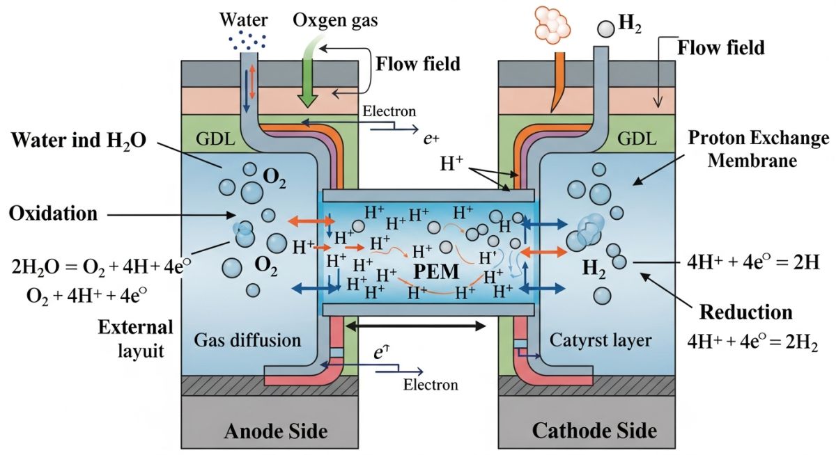
The water splitting process is divided into two distinct half-cell reactions occurring simultaneously on opposite sides of the membrane:
Anode (Oxygen Evolution Reaction – OER):
2H2O -> O2 + 4H+ + 4e-
Cathode (Hydrogen Evolution Reaction – HER):
4H+ + 4e- -> 2H2
At the anode, water is oxidized to produce oxygen gas, free electrons, and protons (H+ ions). The electrons travel through the external electrical circuit to the cathode. Meanwhile, the protons migrate through the acidic polymer membrane to the cathode side. At the cathode, these protons combine with the returning electrons to form high-purity hydrogen gas.
Membrane Technology and Proton Transport
The membrane must act as an efficient proton conductor while remaining an electrical insulator and a physical barrier to gas crossover. If hydrogen and oxygen mix within the stack, it can create a highly combustible mixture. PFSA membranes, such as Nafion, feature a hydrophobic Teflon backbone that provides mechanical strength, coupled with hydrophilic sulfonic acid functional groups that facilitate rapid proton transport.
In my field inspections, I have seen stacks fail prematurely due to water contamination. Even trace amounts of metal ions (such as iron, copper, or sodium) will displace the protons on the sulfonic acid sites. This drastically reduces proton conductivity, increases cell resistance, and leads to localized hot spots that can puncture the membrane. Always ensure your water treatment system delivers ASTM Type II deionized water with a conductivity of less than 0.1 microSiemens per centimeter.
Key Structural Components
A commercial PEM electrolyzer stack consists of multiple cells clamped together. Each cell contains several high-performance materials:
- Catalyst Coated Membrane (CCM): The membrane is coated directly with noble metal catalysts. The anode typically uses iridium oxide (IrO2) to withstand the highly corrosive, acidic, and oxidizing environment. The cathode uses platinum (Pt) to optimize the hydrogen evolution reaction.
- Gas Diffusion Layers (GDL): These porous layers distribute water evenly across the catalyst surfaces and conduct electricity. The anode GDL must be made of sintered titanium felt to resist corrosion, while the cathode GDL can utilize carbon paper or carbon cloth.
- Bipolar Plates (BPPs): These plates separate individual cells, distribute feed water, route product gases via flow fields, and conduct current through the stack. They are typically fabricated from titanium or gold-coated stainless steel to prevent corrosion and hydrogen embrittlement.
Electrochemical Calculations and Efficiency
To evaluate stack performance, we calculate the cell voltage using the Nernst equation and accounting for various overpotentials:
V_cell = V_rev + n_act + n_ohm + n_conc
Where:
• V_rev is the reversible cell voltage (typically 1.23 V at standard temperature and pressure).
• n_act represents activation overpotentials due to charge transfer kinetics at the catalyst surfaces.
• n_ohm represents ohmic losses from electronic and ionic resistance within the membrane, GDLs, and plates.
• n_conc represents concentration overpotentials caused by mass transport limitations of reactants and products.
The specific energy consumption of a PEM electrolyzer typically ranges from 50 to 65 kWh per kilogram of hydrogen produced. This corresponds to an efficiency of 60% to 75% based on the Higher Heating Value (HHV) of hydrogen.
PEM Electrolyzer Explained Operating Parameters
Designing a piping system for a PEM electrolyzer requires a deep understanding of its operating envelope. High operating pressures reduce the energy required for downstream compression, but they also increase the rate of gas crossover. The table below outlines the typical operating parameters for industrial-scale PEM electrolyzers.
| Parameter | Typical Range | Engineering Impact & Design Considerations |
|---|---|---|
| Operating Temperature | 50°C to 80°C | Higher temperatures improve kinetics but accelerate membrane degradation and chemical attack. |
| Operating Pressure | 10 to 35 barg | High pressure reduces downstream compressor duty but increases hydrogen crossover risks. |
| Current Density | 1.0 to 3.0 A/cm² | Determines hydrogen production rate per unit area. Higher density increases ohmic losses. |
| Cell Voltage | 1.8 to 2.2 V | Directly impacts stack efficiency. Voltages above 2.2 V indicate high resistance or degradation. |
| Feed Water Quality | < 0.1 µS/cm | Requires continuous polishing loops to prevent metal ion poisoning of the membrane. |
| Gas Purity (Raw) | > 99.9% H2 | Contains water vapor. Requires a deoxo catalyst and dryer to reach fuel cell grade (99.97%). |
Technical Mapping & Specifications Matrix
To ensure compliance with international safety and design codes, engineers must map physical components to their respective standards and materials.
| System Component | Acronym / Term | Primary Material | Applicable Standard |
|---|---|---|---|
| Proton Exchange Membrane | PEM / PFSA | Perfluorosulfonic Acid | ISO 22734 |
| Anode Catalyst | OER Catalyst | Iridium Oxide (IrO2) | Manufacturer Spec |
| Cathode Catalyst | HER Catalyst | Platinum (Pt) | Manufacturer Spec |
| Bipolar Plates | BPP | Titanium / Coated SS | ASME Section VIII |
| Process Piping | Hydrogen Piping | 316L Stainless Steel | ASME B31.12 |
How to Commission a PEM Electrolyzer?
Commissioning a PEM electrolyzer requires meticulous attention to detail. Because hydrogen is a small, highly flammable molecule, any mechanical or electrical oversight can lead to catastrophic failures. I have compiled this field checklist based on lessons learned from multiple utility-scale installations.
Perform a helium leak test on all hydrogen-carrying lines at 1.1 times the maximum operating pressure. Nitrogen purging must be completed and verified via oxygen sensors before introducing hydrogen.
Confirm that the feed water conductivity is strictly below 0.1 microS/cm. Verify that the online conductivity meter is calibrated and integrated into the emergency shutdown (ESD) loop.
Conduct a megger test on the stack frame to ensure there are no electrical shorts. Verify that the rectifier control loop responds correctly to dynamic load changes without voltage spikes.
Verify that the backup nitrogen purge system has sufficient pressure and volume to purge the stack in the event of an emergency power loss.
Calibrate the lower explosive limit (LEL) sensors in the oxygen stream. Set the alarm threshold at 1.5% H2 in O2, and the automatic shutdown at 2.0% H2 in O2.
Field Case Study: Real-World Application
During the commissioning of a 5 MW PEM electrolyzer plant in northern Germany, the operations team noticed a rapid increase in cell voltage after only 400 hours of operation. The stack efficiency dropped by 8%, and the hydrogen crossover rate began to rise.
Upon investigation, we discovered two primary issues. First, the demineralized water loop was leaching silica from a low-grade glass-reinforced plastic (GRP) storage tank upstream. Second, the plant was cycling its power input from 10% to 100% within seconds to track wind turbine output, causing severe pressure differentials across the membrane.
We implemented a two-phase engineering solution to save the stack and prevent future failures:
- Water Loop Upgrade: Replaced the GRP tank with a 316L stainless steel tank and added an active mixed-bed ion exchange polisher directly upstream of the stack inlet. This restored water conductivity to less than 0.05 microS/cm.
- Control Loop Optimization: Programmed a ramp-rate limiter into the PLC, restricting power swings to a maximum of 5% per second. This allowed the pressure control valves on the hydrogen and oxygen separators to maintain a differential pressure of less than 100 mbar across the membrane.
Engineering Recommendation: When designing balance of plant (BOP) systems for PEM electrolyzers, never compromise on water treatment or control valve speed. Fast-acting control valves and high-purity piping materials are mandatory to protect the expensive catalyst-coated membranes from mechanical stress and chemical poisoning.
Frequently Asked Engineering Questions
What is the typical lifetime of a PEM electrolyzer stack?
Why is titanium used for the anode bipolar plates?
How does dynamic load tracking affect PEM electrolyzers?
What are the main differences between PEM and Alkaline electrolyzers?
What piping standards apply to PEM electrolyzer plants?
How is gas crossover managed in high-pressure PEM stacks?
Complete Course on
Piping Engineering
Check Now
Key Features
- 125+ Hours Content
- 500+ Recorded Lectures
- 20+ Years Exp.
- Lifetime Access
Coverage
- Codes & Standards
- Layouts & Design
- Material Eng.
- Stress Analysis
