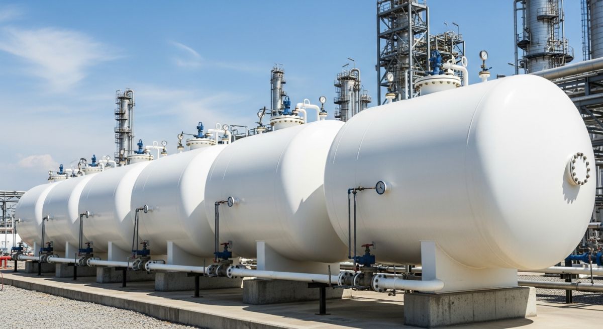
LPG Storage Tanks: Engineering Design, Selection, and Code Calculations
Over my 20 years in piping and pressure vessel design, I have seen how a minor calculation error in LPG storage can lead to catastrophic failures. Liquefied Petroleum Gas (LPG)—primarily a mixture of propane and butane—is a volatile substance with a high liquid-to-gas expansion ratio of approximately 250:1. Storing this medium requires an absolute commitment to structural integrity, precise material selection, and rigorous adherence to international codes.
In this guide, I will share the practical engineering principles, selection criteria, and step-by-step design calculations that I use when designing safe, reliable, and code-compliant storage systems. Whether you are designing aboveground bullets, mounded vessels, or large-scale spherical tanks, this technical breakdown will serve as your definitive engineering reference.
Key Engineering Takeaways
- Understand the critical differences between aboveground bullets, mounded bullets, and spherical Hortonspheres.
- Master the ASME Section VIII Division 1 UG-27 formulas for shell and head thickness calculations.
- Learn how to mitigate Stress Corrosion Cracking (SCC) through mandatory Post-Weld Heat Treatment (PWHT).
- Implement robust safety relief systems in compliance with API 520 and API 521.
How Do We Design LPG Storage Tanks Safely?
LPG Storage Tank Design: The systematic engineering process of sizing, material selection, and stress analysis of pressurized vessels in accordance with ASME Section VIII Division 1 to withstand internal vapor pressures and environmental loads. This process ensures structural integrity under maximum operating pressures and temperatures.
When selecting the configuration for storing LPG, we generally choose between three primary vessel types: aboveground horizontal bullets, mounded horizontal bullets, and spherical vessels (Hortonspheres). Each type serves a specific volumetric and safety profile. Aboveground bullets are typically limited to volumes under 300 cubic meters due to footprint and safety constraints. For larger volumes, spherical vessels offer the most efficient surface-area-to-volume ratio, reducing material costs. Mounded bullets have become the industry standard for high-risk areas because the surrounding earth mound protects the vessel from external fire exposure and potential Boiling Liquid Expanding Vapor Explosions (BLEVE).
Step-by-Step Shell Thickness Calculation
To determine the minimum required thickness of a cylindrical shell under internal pressure, we turn to ASME Section VIII Division 1, paragraph UG-27. The formula for circumferential stress (which typically governs design) is expressed as:
Where:
- t = Minimum required shell thickness (mm)
- P = Internal design pressure (MPa)
- R = Inside radius of the shell (mm)
- S = Maximum allowable stress value of the material (MPa) at design temperature
- E = Joint efficiency factor (dimensionless, ranging from 0.70 to 1.00 based on radiography)
- CA = Corrosion allowance (mm)
Practical Design Example:
Let us calculate the required shell thickness for an aboveground LPG bullet with the following design parameters:
- Design Pressure (P) = 1.72 MPa (approx. 250 psi, corresponding to propane vapor pressure at 55°C)
- Inside Diameter (D) = 3000 mm, which means Inside Radius (R) = 1500 mm
- Material = SA-516 Grade 70 carbon steel
- Allowable Stress (S) at 55°C = 138 MPa
- Joint Efficiency (E) = 1.00 (Fully radiographed longitudinal seams)
- Corrosion Allowance (CA) = 1.50 mm
Substituting these values into our UG-27 formula:
t = 2580 / (138 – 1.032) + 1.5
t = 2580 / 136.968 + 1.5
t = 18.84 + 1.5 = 20.34 mm
Based on this calculation, the minimum required thickness is 20.34 mm. In practice, we round this up to the nearest standard plate thickness, selecting a nominal plate thickness of 22 mm to account for mill under-tolerance.
In my years on site, I have observed that LPG containing trace amounts of hydrogen sulfide (H2S) or wet carbon dioxide can cause severe Stress Corrosion Cracking (SCC) in high-strength carbon steels. To mitigate this risk, it is critical to specify Post-Weld Heat Treatment (PWHT) for all LPG storage vessels, regardless of shell thickness. PWHT tempers the heat-affected zones (HAZ) of welds and reduces residual tensile stresses to safe levels.
Nozzle Reinforcement and External Loads
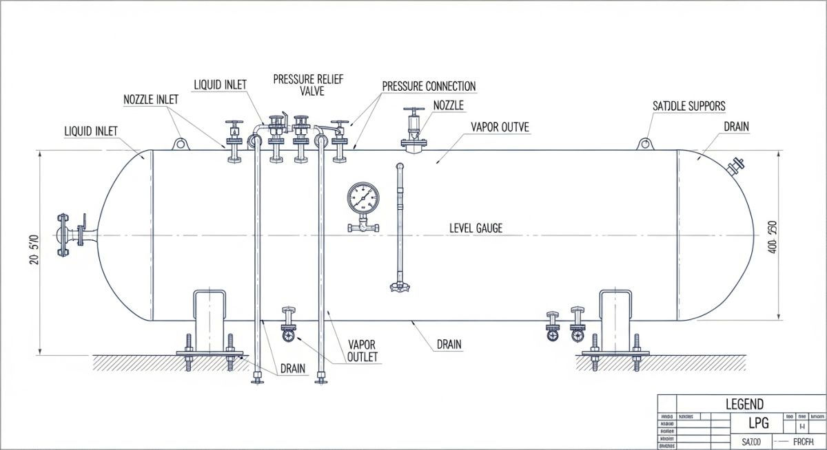
Designing the shell thickness is only half the battle. We must also evaluate nozzle openings for reinforcement under ASME Section VIII Div 1 UG-37. Large nozzles, such as the liquid outlet or the manway, weaken the vessel shell. We must ensure that the metal area removed by the opening is fully compensated by excess thickness in the shell, nozzle neck, or by adding a reinforcing pad (repads). In addition, external piping loads—such as thermal expansion and seismic forces—must be analyzed at the nozzle-to-shell junctions using WRC 107/297 or Finite Element Analysis (FEA) to prevent localized overstressing.
The table below outlines the typical engineering parameters and selection criteria for different types of LPG storage installations. These values represent standard industry practices for mid-to-large scale terminals.
| Storage Type | Typical Volume Range (m³) | Design Pressure (barg) | Common Materials | Primary Safety Advantage |
|---|---|---|---|---|
| Aboveground Bullet | 50 to 300 | 15.5 to 18.0 | SA-516 Gr. 70 / SA-612 | Easy visual inspection and maintenance access |
| Mounded Bullet | 100 to 2,500 | 15.5 to 18.0 | SA-516 Gr. 70 (Low Temp tested) | Complete protection against BLEVE and fire exposure |
| Spherical Tank | 1,000 to 10,000 | 10.0 to 16.0 | SA-537 Class 1 / SA-516 Gr. 70 | Optimized weight-to-volume ratio, small footprint |
| Refrigerated Tank | 10,000 to 100,000 | 0.1 to 0.5 | SA-203 Gr. D/E (Nickel Alloy) | Extremely large capacity at atmospheric pressure |
This matrix maps the core technical entities, structural acronyms, and physical parameters to their governing international standards.
| Entity / Acronym | Technical Description | Physical Parameter / Value | Governing Standard |
|---|---|---|---|
| MAWP | Maximum Allowable Working Pressure at top of vessel | Typically 17.2 barg for propane service | ASME Sec VIII Div 1 |
| MDMT | Minimum Design Metal Temperature to prevent brittle fracture | -46°C to -29°C depending on location | ASME Sec VIII UG-20 |
| SRV / PSV | Safety Relief Valve sizing for overpressure protection | Sized for fire case and thermal expansion | API Standard 520 / 521 |
| Cathodic Protection | Corrosion prevention for buried or mounded vessels | -850 mV relative to copper/copper-sulfate electrode | NACE SP0169 |
How Do We Verify LPG Storage Tanks?
LPG Tank Site Verification: The mandatory field inspection and testing protocol executed prior to commissioning to verify mechanical integrity, safety valve calibration, and foundation stability. This process ensures compliance with local environmental regulations and international safety standards.
Before introducing hydrocarbons into any new or modified LPG storage vessel, a rigorous field verification protocol must be executed. This checklist represents the minimum quality control steps that I enforce during the pre-commissioning phase of a project.
Pre-Commissioning Field Checklist
-
Hydrostatic Test Verification: Confirm that the vessel has undergone a hydrostatic test at 1.3 times the MAWP in accordance with ASME Section VIII Div 1 UG-99. Verify that test water was completely drained and the vessel was thoroughly dried to prevent internal corrosion.
-
Nondestructive Testing (NDT) Records: Review 100% of radiography (RT) films for longitudinal and circumferential welds, and magnetic particle testing (MT) reports for nozzle attachment welds.
-
Safety Relief Valve (SRV) Calibration: Verify that the dual-port SRVs are calibrated, tagged, and installed with three-way manifold valves locked in the correct position to ensure continuous overpressure protection.
-
Cathodic Protection System (Mounded Bullets): Measure and record the structure-to-soil potential to ensure it meets the minimum -850 mV polarization criterion per NACE standards.
-
Foundation Settlement Monitoring: Establish baseline elevation benchmarks on the concrete saddles or sand bed to monitor for differential settlement during the initial water-fill and subsequent product-fill cycles.
Field Case Study: Real-World Application
During a terminal expansion project in Southeast Asia, a newly installed 1,200 m³ mounded LPG bullet experienced unexpected differential settlement of 45 mm at the southern support saddle after the initial hydrostatic test. This settlement exceeded the maximum allowable limit of 15 mm, causing severe bending moments on the connected 8-inch liquid outlet piping and threatening to overstress the vessel nozzle beyond the allowable limits of ASME B31.3.
To resolve this issue, my team immediately halted the commissioning process and performed a comprehensive piping stress analysis using CAESAR II. We redesigned the piping layout by replacing the rigid piping spool with a highly flexible expansion loop containing three 3D bends. This modification absorbed the 45 mm displacement without transferring excessive loads to the nozzle. Additionally, we performed localized compaction grouting beneath the settled saddle to stabilize the foundation, and installed continuous laser telemetry sensors to monitor settlement in real-time.
This case study highlights the critical importance of soil mechanics and piping flexibility in LPG terminal design. When designing mounded bullets, never assume the foundation will remain perfectly rigid. Always design the connected piping with sufficient flexibility to accommodate potential differential settlement.
Key Questions on LPG Storage Tanks Answered
LPG Storage Tank FAQs: A compiled reference of critical engineering queries addressing safety distances, pressure ratings, material selection, and inspection intervals for pressurized LPG vessels.
What is the typical design pressure for LPG storage tanks?
Why is post-weld heat treatment (PWHT) mandatory for LPG vessels?
How does a mounded bullet prevent a BLEVE?
What materials are recommended for low-temperature LPG service?
How often must LPG storage tanks undergo internal inspection?
What is the role of the vacuum breaker valve in LPG tanks?
===FAQ_BLOCK===
Complete Course on
Piping Engineering
Check Now
Key Features
- 125+ Hours Content
- 500+ Recorded Lectures
- 20+ Years Exp.
- Lifetime Access
Coverage
- Codes & Standards
- Layouts & Design
- Material Eng.
- Stress Analysis
