
How to Use a Pump Commissioning Checklist for Start-Up
In my 20-plus years of commissioning heavy industrial piping systems, I have seen millions of dollars in machinery reduced to scrap metal in a matter of seconds. The culprit is almost always the same: a rushed start-up. Skipping a single pre-start step can lead to dry running, catastrophic mechanical seal failure, or bent shafts. That is why a structured, field-verified pump commissioning checklist is not just a piece of paperwork—it is your primary defense against operational disaster.
When we commission a pump, we are not just turning on a switch. We are integrating a complex hydraulic machine into a pressurized piping network. Every valve position, instrument calibration, and shaft alignment tolerance must be verified under strict engineering guidelines. In this guide, I will share the exact field protocols and calculations I use to ensure a safe, efficient, and reliable pump start-up.
Key Commissioning Takeaways
- Eliminate piping strain before tightening flange bolts to prevent casing distortion.
- Verify driver rotation with the coupling spacer removed to avoid mechanical seal damage.
- Ensure the pump casing is fully vented and primed to prevent dry running.
- Establish baseline vibration and temperature readings during the first 4 hours of operation.
Why a Pump Commissioning Checklist Prevents Failures
Before the first drop of fluid is pumped, several critical engineering parameters must be calculated and verified. The most common cause of early-stage pump failure is cavitation, which occurs when the Net Positive Suction Head Available (NPSHa) is less than the Net Positive Suction Head Required (NPSHr).
Net Positive Suction Head (NPSH) Calculation
To ensure the pump does not cavitate during start-up, I always calculate the NPSHa using the following formula:
Where:
- hp = Absolute pressure on the liquid surface in the suction vessel (expressed in meters of liquid head).
- hs = Static height of the liquid level above or below the pump centerline (positive for flooded suction, negative for suction lift).
- hf = Friction losses in the suction piping system at the design flow rate.
- hvp = Vapor pressure of the liquid at the operating temperature.
To prevent cavitation, NPSHa must exceed the NPSHr (provided by the pump manufacturer) by a safety margin of at least 1.0 meter or a ratio of 1.15, in accordance with ANSI/HI 9.6.1.
Thermal Expansion and Shaft Alignment
Another critical calculation is the vertical thermal growth of the pump and driver. When pumping hot fluids, the pump casing expands vertically. If this is not compensated for during cold alignment, the shafts will become misaligned at operating temperature, leading to high vibration and bearing failure.
Where:
- DY = Vertical thermal growth (in millimeters).
- alpha = Coefficient of thermal expansion of the material (e.g., 0.000012 per degree Celsius for carbon steel).
- L = Distance from the machine base to the shaft centerline (in millimeters).
- DT = Temperature difference between operating and ambient conditions (in degrees Celsius).
Minimum Flow Bypass Sizing
Operating a pump below its Minimum Continuous Stable Flow (MCSF) causes internal recirculation, high vibration, and rapid temperature rise. The minimum flow bypass line must be sized using the thermal rise formula:
Where:
- Qmin = Minimum continuous stable flow rate (cubic meters per hour).
- P = Power input at shutoff (kilowatts).
- density = Liquid density (kilograms per cubic meter).
- Cp = Specific heat capacity of the liquid (kilojoules per kilogram Kelvin).
- DTmax = Maximum allowable temperature rise (typically 5 to 10 Kelvin to prevent vapor flashing).
Standard Alignment Tolerances for Industrial Pumps
| Operating Speed (RPM) | Max Radial Offset (mm) | Max Angular Offset (degrees) | Coupling Type |
|---|---|---|---|
| 0 – 1000 | 0.15 | 0.09 | Flexible Element |
| 1001 – 1800 | 0.10 | 0.06 | Flexible Element |
| 1801 – 3600 | 0.05 | 0.03 | Spacer Coupling |
| > 3600 | 0.03 | 0.02 | High-Performance Gear |
Key Commissioning Parameters and Code References
| Parameter | Target Range | Code Reference | Field Verification Method |
|---|---|---|---|
| Piping Strain | < 0.05 mm dial movement | API 686 Ch. 6 | Dial indicators on coupling during flange bolt-up |
| Shaft Runout | < 0.025 mm TIR | API 610 Sec. 9.3 | Dial indicator sweep on shaft sleeve |
| Vibration Velocity | < 3.0 mm/s RMS | ISO 10816-3 | Triaxial accelerometer on bearing housings |
| Bearing Temp | < 82 degrees C | API 610 Sec. 6.10 | RTD sensors or infrared thermography |
| Seal Flush Flow | Per API Plan spec | API 682 | In-line rotameter or pressure differential |
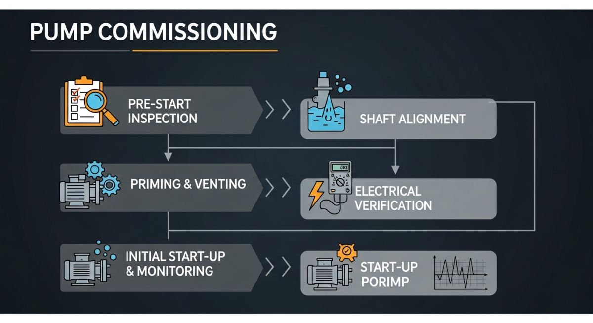
Executing the Pump Commissioning Checklist Onsite
This checklist must be executed in sequence by qualified mechanical technicians and signed off by the commissioning engineer before power is applied to the driver.
Pre-Start & Alignment Verification Checklist
Field Case Study: Real-World Application
The Problem: Catastrophic Seal Failure on Start-Up
During the commissioning of a multi-stage boiler feed pump (API 610 Type BB3) at a combined-cycle power plant, the field crew bypassed the piping strain check on the suction line to meet a tight schedule. Within 15 minutes of initial start-up, the pump experienced severe vibration levels exceeding 12.5 mm/s RMS at the outboard bearing, followed by a massive leak from the drive-end mechanical seal. The pump was shut down immediately.
The Outcome: Stress-Free Realignment
I was called to the site to troubleshoot. We uncoupled the pump and mounted dial indicators on the coupling hub. When we unbolted the suction flange, the pump shaft jumped 0.85 mm vertically and 1.2 mm horizontally, indicating massive piping strain. The piping was cut, re-fit, and welded stress-free. After replacing the mechanical seal and realigning the pump to within 0.03 mm, we restarted the unit. Vibration levels dropped to a stable 1.4 mm/s RMS, and the pump has operated continuously for over three years without issue.
This case proves that skipping steps on a pump commissioning checklist to save a few hours always results in days of downtime and thousands of dollars in repair costs.
Frequently Asked Engineering Questions
Why must the driver be uncoupled during the motor rotation check?
What is the maximum allowable piping strain on pump nozzles?
How do you properly vent a pump with a flooded suction?
What are the acceptable vibration limits during commissioning?
Why is a soft foot check necessary before final alignment?
How long should a pump run during its initial mechanical test?
===FAQ_BLOCK===
Complete Course on
Piping Engineering
Check Now
Key Features
- 125+ Hours Content
- 500+ Recorded Lectures
- 20+ Years Exp.
- Lifetime Access
Coverage
- Codes & Standards
- Layouts & Design
- Material Eng.
- Stress Analysis

