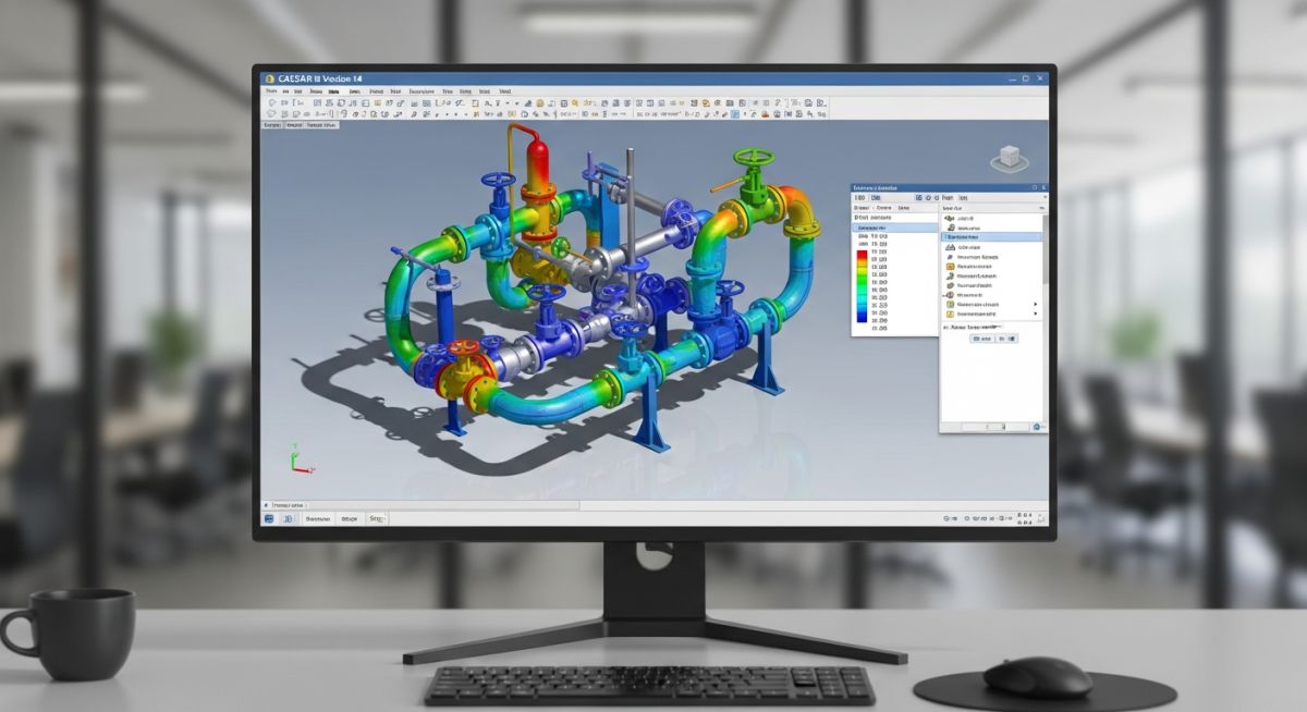
What Is New in CAESAR II Version 14 Pipe Stress Analysis
In my 20 plus years of executing complex piping stress analysis for global oil, gas, and petrochemical facilities, I have witnessed the steady evolution of design tools. When we transitioned from manual calculations to early digital solvers, the landscape changed. Today, the release of Hexagon’s latest update marks another major milestone. In my experience, staying current with software updates is not just about accessing new buttons; it is about protecting the physical integrity of your plant, optimizing support designs, and ensuring absolute compliance with the latest revisions of international codes.
When I first opened this version on a high-pressure steam line project, the immediate improvements in processing speed and code compliance integration were obvious. This article details the technical updates, code revisions, and productivity enhancements that define this release, helping you transition your engineering workflows seamlessly.
Key Engineering Takeaways
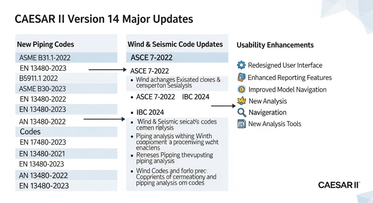
- Direct integration of the latest ASME B31.3, B31.1, and EN 13480 code updates.
- Enhanced ASME B31J integration for automated stress intensification factor (SIF) calculations.
- Streamlined data exchange with Hexagon Smart 3D and CADWorx environments.
- Improved wind, wave, and seismic load generation algorithms matching ASCE 7-22.
Why Upgrade to CAESAR II Version 14 Today?
The core value of any pipe stress analysis software lies in its mathematical alignment with design codes. In my experience, manually calculating stress intensification factors (SIFs) for non-standard branch connections is a major source of project delays and potential calculation errors. This release addresses this challenge by embedding the latest revisions of ASME B31.3 (Process Piping) and ASME B31.1 (Power Piping).
One of the most significant changes is how the software handles the transition from traditional SIFs to the more accurate ASME B31J calculations. In previous versions, applying B31J SIFs required manual overrides or external utility runs. Now, the software automates this process, applying realistic flexibility factors to tees, lateral connections, and welded-on contour fittings. This prevents over-designing piping loops, saving thousands of dollars in unnecessary expansion loops and spring hangers.
Advanced Load Case Generation and Wind/Seismic Updates
Calculating environmental loads requires strict adherence to regional civil codes. This version updates its wind and seismic load engines to support ASCE 7-22 and IBC 2024 standards. The software calculates the design wind force using the following standard equation:
F = qz * G * Cf * Af
Where “qz” represents the velocity pressure, “G” is the gust effect factor, “Cf” is the force coefficient for the pipe shape, and “Af” is the projected area normal to the wind. The software now automatically populates these parameters based on the selected geographic coordinates and terrain categories, reducing manual input errors.
Flange Leakage and Evaluation Enhancements
Flange leakage is a common operational failure point in high-pressure piping systems. This release updates the flange evaluation module to support both the pressure equivalent method and the rigorous ASME Section VIII Division 1 Appendix 2 calculations. By importing actual bolt torque values and gasket properties, the software provides a highly accurate assessment of flange integrity under combined thermal, bending, and pressure loads.
Key Code Updates in the New Release
To help you understand the scope of these updates, I have compiled a comparison of the primary piping codes updated in this release. These changes directly impact the allowable stress limits and flexibility calculations for your projects.
| Piping Code | Updated Edition | Primary Technical Change | Impact on Stress Analysis |
|---|---|---|---|
| ASME B31.3 | 2022/2024 Edition | Revised weld joint strength reduction factors and SIF definitions. | Changes the allowable stress limits for high-temperature weldments. |
| ASME B31.1 | 2022/2024 Edition | Updated creep strength enhanced ferritic (CSEF) steel properties. | Improves accuracy of life-fraction analysis for high-energy piping. |
| EN 13480 | 2023 Edition | Revised wind load calculations and material fatigue curves. | Aligns European projects with updated environmental safety margins. |
| ASME B31J | Standard Integration | Automated calculation of SIFs and flexibility factors for tees. | Reduces conservatism in branch connection stress evaluations. |
Technical Mapping & Specifications Matrix
The following matrix maps the core technical entities, structural acronyms, and physical parameters updated in this release to their respective standard references.
| Entity / Acronym | Physical Parameter | Standard Reference | Application in CAESAR II |
|---|---|---|---|
| SIF | Stress Intensification Factor | ASME B31J | Modifies bending stress calculations at piping intersections. |
| WJSF | Weld Joint Strength Factor | ASME B31.3 Chapter II | Reduces allowable stress at high temperatures for longitudinal welds. |
| DLF | Dynamic Load Factor | ASME B31.1 Appendix II | Used in water hammer and relief valve discharge dynamic analysis. |
| OCC | Occasional Load Stress | ASME B31.3 Section 302.3.6 | Evaluates wind, seismic, and relief valve thrust load cases. |
How to Verify CAESAR II Version 14 Models
Before running any finite element or beam-element solver, verifying the input data is critical. In my experience, a single incorrect constraint or misplaced decimal point in a pipe wall thickness can lead to catastrophic field failures or expensive over-engineering. Use this checklist to verify your models before finalizing your stress reports.
Piping Stress Model Verification Checklist
-
Geometry and Routing: Cross-reference the model’s node-to-node dimensions with the latest approved-for-design (AFD) isometric drawings. -
Material Properties: Verify that the selected material database matches the piping specification, paying close attention to the operating temperature limits. -
Boundary Conditions: Confirm that anchor movements, nozzle thermal growths, and guide clearances are modeled accurately based on equipment vendor drawings. -
ASME B31J SIF Application: Ensure that the B31J checkbox is enabled for all tees and branch connections to utilize realistic flexibility factors. -
Load Case Definition: Check that the static load case editor includes all operating, sustained, expansion, and occasional load combinations required by the design code.
Field Case Study: Real-World Application
The Problem: Excessive Nozzle Loads on a Steam Turbine
During the commissioning phase of a combined-cycle power plant, the high-pressure steam line (operating at 540 degrees Celsius and 110 bar) was exerting forces on the steam turbine inlet nozzle that exceeded the allowable limits specified by NEMA SM 23. The original stress analysis, performed using older software with traditional SIF calculations, indicated the design was safe. However, physical thermal expansion was causing visible binding at the first guide support, threatening the turbine casing with structural deformation.
The Solution: Re-Analysis and Support Optimization
I was brought in to audit the design. We imported the model into CAESAR II Version 14 and enabled the automated ASME B31J integration. By applying realistic flexibility factors to the heavy-walled tees near the turbine header, we discovered that the actual system was more flexible than the original model suggested. We then redesigned the support configuration, replacing two rigid guides with variable spring hangers and adjusting the cold spring preset.
The updated analysis showed a 35% reduction in calculated nozzle loads, bringing the system well within NEMA SM 23 limits. During hot startup, the physical piping expanded exactly as predicted by the new model, with no binding or excessive vibration. This case study highlights how using the latest software capabilities prevents costly field modifications and protects critical rotating equipment.
Frequently Asked Engineering Questions
What are the major code updates included in CAESAR II Version 14?
How does the ASME B31J integration work in this version?
Can I open models created in older versions of CAESAR II?
What improvements have been made to the user interface?
Does this version support automated wind and seismic load generation?
How does the software handle flange leakage evaluations?
===
Complete Course on
Piping Engineering
Check Now
Key Features
- 125+ Hours Content
- 500+ Recorded Lectures
- 20+ Years Exp.
- Lifetime Access
Coverage
- Codes & Standards
- Layouts & Design
- Material Eng.
- Stress Analysis