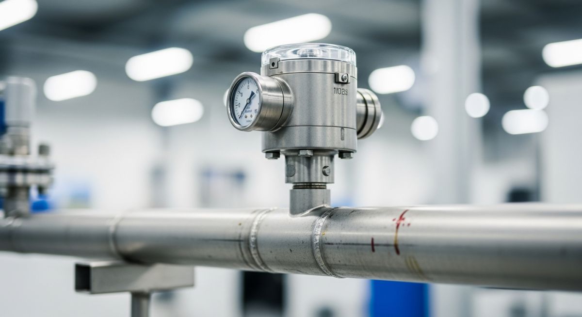
What is a Pressure Switch? Working, Types, and Selection Guide
In my 20-plus years of commissioning piping systems and refinery instrumentation, I have seen millions of dollars in equipment saved by a simple, fifty-dollar pressure switch. Conversely, I have also stood on-site looking at ruptured vessels because someone selected the wrong sensing element or miscalculated the deadband. These devices are the silent sentinels of our plants. They do not just measure pressure; they act as the final line of defense before a relief valve pops or a pump runs dry.
Understanding how these instruments operate, their mechanical variations, and how to select them for harsh process environments is a fundamental skill for any piping or instrumentation engineer. Whether you are dealing with high-vibration hydraulic lines or highly corrosive chemical processes, the right pressure switch ensures your system remains safe, predictable, and fully compliant with industrial codes.
Key Engineering Takeaways
- Discover the core mechanical force-balance principles that drive pressure switch actuation.
- Compare the performance limits of diaphragm, bellows, and piston sensing elements.
- Learn how to calculate and adjust deadband to prevent destructive switch chattering.
- Master the selection criteria based on process fluid compatibility, electrical ratings, and hazardous area classifications.
How Does a Pressure Switch Work Safely?
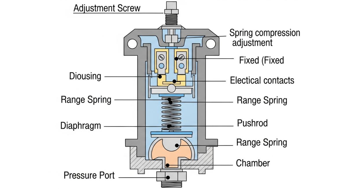
At its core, an electromechanical pressure switch operates on a simple force-balance principle. The process fluid enters the pressure port and exerts a force against a sensing element, such as a diaphragm or piston. This force is directly proportional to the process pressure and the surface area of the sensing element.
Opposing this fluid force is a calibrated range spring. The tension of this spring is adjusted via a setpoint screw. When the process pressure rises to the point where the force on the sensing element exceeds the opposing force of the range spring, the sensing element moves. This physical movement is transmitted through a piston or pushrod to actuate an electrical microswitch, changing the state of the contacts from normally open (NO) to normally closed (NC), or vice versa.
The Force Balance Equation:
As the process pressure decreases, the fluid force drops below the spring force. The range spring then pushes the sensing element back to its original position, resetting the microswitch. The difference between the actuation point (setpoint) and the de-actuation point (reset point) is known as the deadband or hysteresis. Managing this deadband is critical; if it is too narrow, the switch will “chatter” (rapidly cycle on and off) when the process pressure fluctuates slightly around the setpoint, leading to premature electrical and mechanical failure.
In my experience, setting a deadband too tight on a high-flow pipeline is a recipe for disaster. The resulting high-frequency cycling can burn out microswitch contacts within hours and cause severe water hammer in downstream piping due to rapid valve actuation. Always ensure your deadband is wider than the normal process pressure ripple.
Understanding Sensing Element Variations
The choice of sensing element dictates the pressure switch’s sensitivity, pressure range, and cycle life. The three primary types used in industrial applications are:
- Diaphragm Switches: These utilize a flexible metal or elastomer membrane. They are highly sensitive and ideal for low-pressure applications (vacuum up to 10 bar). Because the diaphragm has a large surface area, it can detect minute pressure changes.
- Bellows Switches: These use a metallic bellows that expands and contracts like an accordion. They offer a good balance between sensitivity and pressure range, making them suitable for medium-pressure applications (up to 100 bar) where high accuracy is required.
- Piston Switches: These employ a rugged metal piston sealed by an O-ring. They are designed for high-pressure systems (up to 700 bar) and are highly resistant to severe pressure surges and hydraulic shocks. However, they are less sensitive than diaphragm or bellows designs and are subject to O-ring wear over high cycles.
Selecting the Right Pressure Switch Sensing Element
| Sensing Element | Pressure Range | Repeatability | Cycle Life | Fluid Compatibility | Primary Application |
|---|---|---|---|---|---|
| Elastomeric Diaphragm | Vacuum to 15 bar | Excellent (±0.5%) | High (>1 million) | Air, Water, Light Oils | Pneumatic loops, HVAC systems |
| Metallic Bellows | 0.5 to 100 bar | Very Good (±1.0%) | Moderate | Steam, Corrosive Gases | Boiler pressure control |
| Piston with O-Ring | 10 to 700 bar | Good (±2.0%) | Very High | Hydraulic Fluids, Heavy Oils | Hydraulic power units |
| Welded Metal Diaphragm | Vacuum to 150 bar | Excellent (±0.5%) | High | Corrosive Chemicals, Acids | Refinery process lines |
| Specification Parameter | Technical Definition | Standard Reference | Engineering Impact |
|---|---|---|---|
| SPDT / DPDT | Single/Double Pole Double Throw electrical contact configuration. | UL 508 | Determines the number of independent circuits the switch can control simultaneously. |
| Proof Pressure | The maximum pressure the device can withstand without permanent deformation. | ASME B40.100 | Prevents mechanical failure during transient pressure surges or water hammer events. |
| Ingress Protection (IP) | Environmental sealing rating for dust and water resistance (e.g., IP66, NEMA 4X). | IEC 60529 | Ensures the electrical enclosure survives outdoor, washdown, or corrosive atmospheres. |
| Intrinsically Safe (Ex ia) | Design methodology limiting electrical energy to prevent ignition of explosive gases. | IEC 60079-11 | Mandatory for switches installed in Class I, Div 1 or Zone 0 hazardous areas. |
How to Verify Pressure Switch Installation On-Site
Before any process line is pressurized, the instrumentation team must execute a rigorous verification protocol. A single loose terminal or a misaligned block valve can render a safety switch useless. In my field audits, I use this structured checklist to ensure zero-defect handovers.
Pre-Commissioning Field Checklist
Verify the switch is mounted free from excessive piping vibration. Ensure the process port points downwards to prevent sediment accumulation inside the sensing chamber.
Confirm a block-and-bleed valve manifold is installed. This allows the switch to be isolated and vented safely for on-site calibration without shutting down the process line.
In hazardous areas, verify that the conduit seal (e.g., Chico fitting) is poured and cured. This prevents explosive gases from migrating through the conduit system.
Perform a 3-point calibration check using a portable hand pump and a certified reference gauge. Document the exact rising setpoint, falling reset point, and calculated deadband.
Check the continuity of the ground wire to the switch enclosure. Verify that the loop resistance matches the design drawings and that the control room receives the correct discrete signal.
Field Case Study: Real-World Application
During the commissioning of a heavy crude oil pumping station, the main hydraulic control unit experienced frequent, unexplained shutdowns. The control room received “low hydraulic pressure” alarms, tripping the main pumps.
The installed instrument was an ultra-sensitive elastomer diaphragm pressure switch. Because the hydraulic pump generated high-frequency pressure pulsations (up to 5 bar ripples at 150 bar operating pressure), the sensitive diaphragm switch was constantly flexing. This caused the microswitch contacts to chatter, eventually welding them shut and triggering false low-pressure trips.
I led the troubleshooting team on-site. We immediately decommissioned the elastomer diaphragm switch and implemented a two-fold solution:
- We replaced the diaphragm switch with a heavy-duty, piston-actuated pressure switch designed for high-cycle hydraulic service.
- We installed a mechanical piston snubber (pulsation damper) directly upstream of the switch inlet to smooth out the high-frequency pressure spikes.
- We adjusted the switch deadband to 12 bar, safely wider than the pump’s operating pressure ripple.
Following these modifications, the false trips ceased entirely. The system has now operated for over four years without a single unplanned shutdown, saving the operator an estimated 120,000 in lost production time.
My direct recommendation for any high-pressure hydraulic or reciprocating pump application is to avoid highly sensitive diaphragm switches. Always specify a piston-actuated switch paired with a dampening device to isolate the internal mechanics from destructive process dynamics.
Frequently Asked Engineering Questions
What is the difference between a pressure switch and a pressure transmitter?
How do you adjust the deadband on an electromechanical pressure switch?
Why is a diaphragm seal used with a pressure switch?
What does “proof pressure” mean, and how does it differ from “burst pressure”?
Can I use an AC-rated pressure switch in a DC control circuit?
How often should industrial pressure switches be calibrated?
===
Complete Course on
Piping Engineering
Check Now
Key Features
- 125+ Hours Content
- 500+ Recorded Lectures
- 20+ Years Exp.
- Lifetime Access
Coverage
- Codes & Standards
- Layouts & Design
- Material Eng.
- Stress Analysis

