Table of Contents
Understanding Difference between ASME B16.47 Series A and Series B Flanges
In my 20-plus years of piping engineering, I have seen many young engineers make the costly mistake of mixing up Series A and Series B flanges on the construction site. They look at a piping layout, see “NPS 36 Class 150,” and assume any flange of that size will bolt together. It is a painful lesson when they discover during field fit-up that the bolt circles do not align, the bolt diameters are completely different, and the gaskets are incompatible.
Understanding the physical and structural differences between these two series is not just an academic exercise; it is a fundamental requirement for ensuring the mechanical integrity of large-diameter piping systems. Let us dive deep into the design philosophies, dimensional variations, and practical field realities of these critical components.
Key Engineering Takeaways
- Zero Intermateability: Series A and Series B flanges cannot be bolted together under any circumstances due to completely different bolt circle diameters and bolt quantities.
- Structural Integrity: Series A flanges are significantly thicker, heavier, and stronger, making them the preferred choice for process piping subjected to high external loads.
- Economic Optimization: Series B flanges are lighter and use smaller, more numerous bolts, offering a highly compact and cost-effective solution for pipeline applications.
- Historical Roots: Series A originates from the MSS SP-44 standard, while Series B is derived from the API 605 standard.
Difference between ASME B16.47 Series A and Series B Flanges
To truly grasp the difference between these two flange series, we must look at their design philosophies. Series A flanges are designed to be robust, heavy-duty connectors. They are built to withstand not only internal pressure but also significant external piping loads, such as bending moments, shear forces, and thermal expansion stresses. This makes them the industry standard for process plants, refineries, and chemical facilities governed by ASME B31.3 Process Piping.
On the other hand, Series B flanges are designed with optimization and compactness in mind. They are thinner, lighter, and utilize a larger number of smaller-diameter bolts. This design minimizes the flange width and weight, which is highly advantageous in pipeline transportation systems governed by ASME B31.4 or ASME B31.8. In these applications, the piping is typically well-supported or buried, meaning external bending moments are minimal, and the primary stress is hoop stress from internal pressure.
Structural Mechanics & Bolting Calculations
Let us look at the structural mechanics of these flanges. Under ASME Section VIII Division 1 Appendix 2, the design of a flange is governed by the total bolt load required to seat the gasket and resist internal pressure.
The minimum required bolt load for operating conditions (Wm1) is calculated as:
Where:
– H is the total hydrostatic end force.
– Hp is the joint compression load.
– G is the gasket reaction diameter.
– P is the design pressure.
– b is the effective gasket width.
– m is the gasket factor.
Because Series A flanges have a larger gasket reaction diameter (G) and wider gaskets, they require a much higher bolt load (Wm1) to maintain a tight seal under pressure. This necessitates larger-diameter bolts. For example, an NPS 36 Class 150 Series A flange uses 32 bolts of 1-1/2 inch diameter.
Conversely, Series B flanges use a narrower gasket and a smaller gasket reaction diameter, reducing the required bolt load. This allows the design to use smaller bolts, such as 44 bolts of 1-1/8 inch diameter for an NPS 36 Class 150 Series B flange.
Bending Moment Resistance
In my experience, the most common failure mode for large-diameter flanges in process plants is not internal pressure, but external bending moments caused by thermal expansion of the piping. The thicker flange ring and larger bolts of Series A provide a significantly higher moment of inertia and resistance to flange rotation.
If you install a Series B flange in a location subjected to high piping stress, the flange ring is highly susceptible to cupping or warping. This rotation unloads the gasket, leading to chronic, hard-to-stop leaks. Therefore, Series A remains the undisputed choice for piping connected to heavy rotating equipment, such as compressors and pumps, where nozzle loads must be strictly controlled.
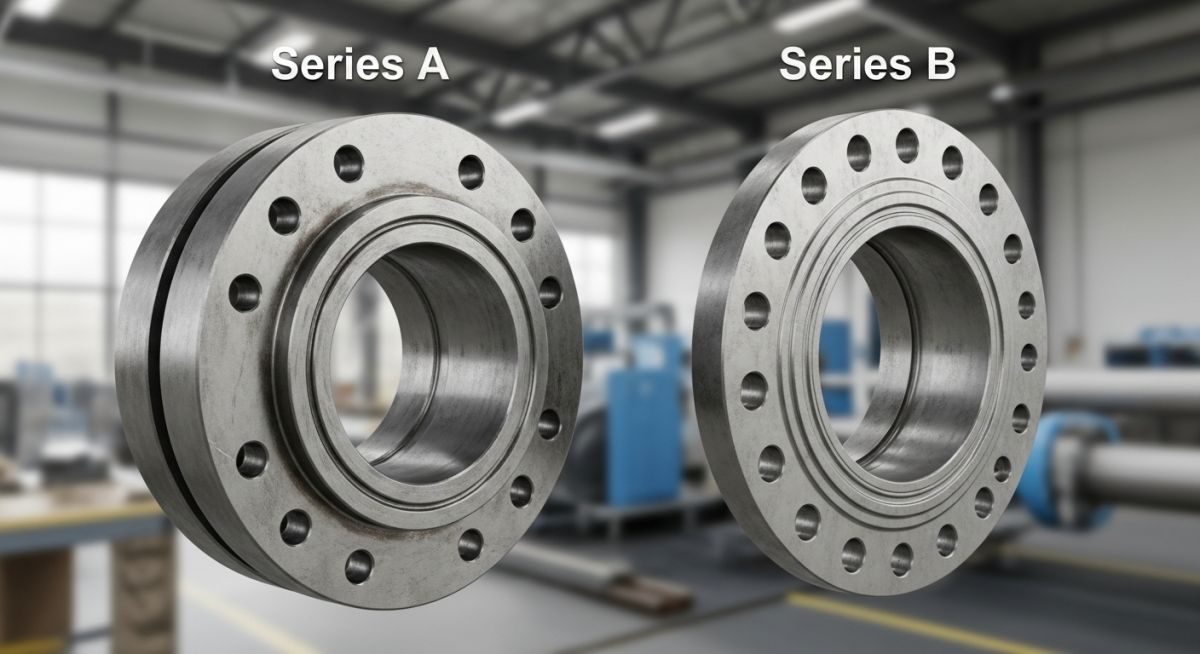
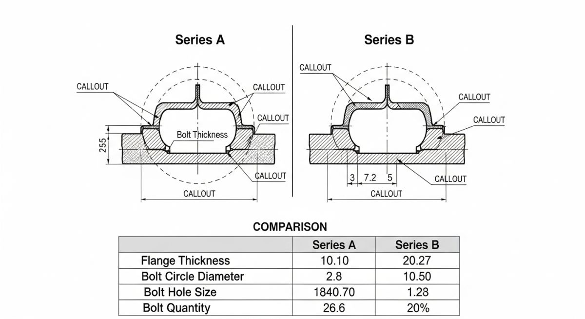
NPS 36 Class 150 and Class 300 Dimensional Data
The table below highlights the stark physical differences between Series A and Series B flanges for a standard NPS 36 pipe size. Note how Series A is consistently thicker, heavier, and uses larger bolts.
| Flange Parameter (NPS 36) | Class 150 Series A | Class 150 Series B | Class 300 Series A | Class 300 Series B |
|---|---|---|---|---|
| Outside Diameter (in) | 46.00 | 43.00 | 47.50 | 44.00 |
| Flange Thickness (in) | 3.56 | 2.38 | 4.50 | 3.12 |
| Bolt Circle Diameter (in) | 42.75 | 39.75 | 44.00 | 40.25 |
| Number of Bolts | 32 | 44 | 32 | 40 |
| Bolt Diameter (in) | 1.50 | 1.125 | 2.00 | 1.50 |
| Approx. Weight (lbs) | 970 | 590 | 2,150 | 1,180 |
This matrix maps the core technical entities, design standards, and physical parameters that define the operational boundaries of both flange series.
| Technical Entity | ASME B16.47 Series A | ASME B16.47 Series B | Reference Standard |
|---|---|---|---|
| Legacy Standard | MSS SP-44 | API 605 | MSS SP-44 / API 605 |
| Primary Application | Process Piping, Equipment Nozzles | Pipelines, Compact Spaces | ASME B31.3 vs ASME B31.4/B31.8 |
| Bolting Characteristics | Fewer, larger-diameter bolts | More, smaller-diameter bolts | ASME B18.2.1 |
| External Load Resistance | High (Excellent bending resistance) | Low to Moderate | ASME Section VIII Div 1 App 2 |
| Relative Cost & Weight | Higher cost, heavier profile | Lower cost, lighter profile | Industrial Market Standards |
Verifying Flange Specifications on Site
Before any large-diameter flange is welded to a pipe spool or bolted into a piping system, the QA/QC team must perform a physical verification. Relying solely on the paperwork is a recipe for disaster. Use this checklist on your job site to ensure 100% compliance.
QA/QC Flange Inspection Checklist
-
Verify Flange Stamping: Check the outer rim of the flange for the mandatory ASME B16.47 marking. It must explicitly state “SER A” or “SER B” alongside the material grade (e.g., ASTM A105 or A350 LF2).
-
Count the Bolt Holes: Physically count the number of bolt holes. If you have an NPS 36 Class 150 flange and count 32 holes, it is Series A. If you count 44 holes, it is Series B.
-
Measure Flange Thickness: Use a calibrated vernier caliper to measure the flange ring thickness (excluding the hub). Compare this measurement directly with the ASME B16.47 dimensional tables.
-
Check Gasket Compatibility: Ensure the gasket outer diameter matches the flange face. A Series A gasket will overlap the bolt holes of a Series B flange, preventing bolt insertion.
-
Confirm Bolt Torque Specifications: Series B flanges use smaller bolts and require significantly lower torque values than Series A. Ensure the torque wrench settings match the specific series to avoid over-stretching the bolts.
Field Case Study: Real-World Application
The Problem: The 45,000 Flange Mismatch
During a major refinery expansion project in 2024, the engineering team specified an NPS 36 Class 300 control valve for a critical gas bypass line. The valve manufacturer supplied the valve with ASME B16.47 Series A flange connections, which was standard for their heavy-duty valve bodies.
However, the piping fabrication shop, looking to save weight and cost on the long pipeline run leading to the valve, fabricated the companion piping spools using ASME B16.47 Series B flanges. The mismatch went unnoticed during the design review because the piping isometric drawings simply labeled the connections as “36-inch Class 300 Flange” without specifying the series.
When the spools were lifted into place on the pipe rack for final bolt-up to the control valve, the construction crew found it physically impossible to align the bolt holes. The Series A valve had 32 bolt holes of 2-inch diameter, while the Series B companion flange had 40 bolt holes of 1-1/2-inch diameter. The project ground to a halt.
The Outcome & Resolution
I was called to the site to assess the situation. Since the control valve body could not be modified, the only viable engineering solution was to cut off the Series B companion flanges from the fabricated piping spools and weld new Series A flanges in their place.
This rework required mobilizing specialized welders, performing post-weld heat treatment (PWHT) on the heavy-wall piping, and re-conducting non-destructive testing (NDT) and hydrotesting. The mistake cost the project 45,000 in direct material and labor costs, and more importantly, delayed the commissioning of that piping loop by 4 critical days.
My Direct Recommendation: Always explicitly state the flange series (Series A or Series B) on all piping isometric drawings, material take-offs (MTOs), purchase orders, and valve data sheets. Never leave the flange series unspecified for any pipe size NPS 26 or larger.
Understanding the Difference between ASME B16.47 Series A and Series B Flanges
Can I bolt an ASME B16.47 Series A flange to a Series B flange?
Why are Series A flanges so much heavier than Series B flanges?
Which series is more cost-effective for large-diameter pipelines?
How do I choose between Series A and Series B for a process plant?
Are the gaskets for Series A and Series B flanges interchangeable?
What are the historical origins of Series A and Series B?
===
Complete Course on
Piping Engineering
Check Now
Key Features
- 125+ Hours Content
- 500+ Recorded Lectures
- 20+ Years Exp.
- Lifetime Access
Coverage
- Codes & Standards
- Layouts & Design
- Material Eng.
- Stress Analysis

📚 Recommended Resources: ASME B16.47 Series A vs Series B
Read these Guides
🎓 Advanced Training


Related posts:
![An engineer performing an API 579 fitness for service assessment on an industrial pressure vessel.]()
How to Perform API 579 Fitness for Service Assessment
![3D CAD render of a bolted flange joint assembly showing a compressed gasket.]()
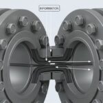
Understanding Gasket m and y Factors in Flange Design
![PASS/START-PROF 4.86 pipe stress analysis software interface displaying a 3D piping model.]()
PASS/START-PROF 4.86 Released: Discover the New Pipe Stress Analysis Capabilities
![ASME certification mark stamped on an industrial pressure vessel nameplate]()
What is ASME Certification? Procedure and Mark Explained
![Professional technician inserting a high-pressure hydro jetting nozzle into a sewer pipe cleanout.]()
What is Hydro Jetting and How Does It Work?
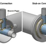
![Side-by-side comparison diagram of stub-in and stub-on piping branch connections.]()
Stub-in vs Stub-on Piping Connections: Engineering Design Guide