
Mastering the Piping Installation and Erection Procedure in Plants
In my 20 plus years of managing mechanical construction on heavy industrial sites, I have seen millions of dollars wasted simply because a field crew tried to force a piping spool into place. Piping erection is not a brute-force exercise; it is a highly coordinated discipline of structural alignment, metallurgy, and stress management. When a piping system is installed with residual stresses, it acts like a loaded spring, waiting to transfer those destructive forces directly into your expensive pumps, compressors, or turbines.
My experience has taught me that a successful installation relies on strict adherence to a documented sequence. From the moment spools are received on-site to the final torqueing of flange bolts, every step must be controlled. This guide breaks down the exact procedures, calculations, and field realities that I use to ensure piping systems are erected safely, on schedule, and with zero operational strain.
- Pre-erection spool inspection prevents costly field re-welds and alignment delays.
- Flange alignment tolerances must be verified and documented before final bolt torqueing.
- Temporary supports must never be substituted for permanent structural anchors during erection.
- Cold spring execution requires explicit engineering approval and real-time monitoring.
- Hydrostatic testing boundaries must be completely isolated from sensitive rotating equipment.
Executing the Piping Installation and Erection Procedure
Erection Sequence Control: This systematic mechanical workflow coordinates spool transport, temporary rigging, structural alignment, and final weld-out under AWS D1.1 and ASME Section IX guidelines. It ensures that structural loads are distributed correctly without inducing residual stresses in the piping system.
The physical erection of piping begins long before the crane lifts a spool. I always insist on a comprehensive pre-erection check. This involves verifying that all concrete foundations, structural steel supports, and equipment nozzles are fully cured, aligned, and signed off by the civil and structural teams. Trying to hang pipe on steel that is not fully bolted or grouted is a recipe for structural failure.
Spool Handling and Rigging Controls
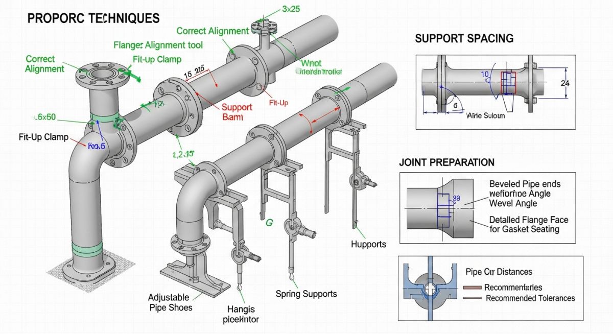
When lifting fabricated spools, rigging points must be carefully selected to prevent bending or deformation. For stainless steel or alloy piping, I enforce the use of nylon slings or rubber-coated chains. Carbon steel chains must never touch stainless steel spools, as iron contamination will compromise the passive oxide layer of the stainless steel, leading to rapid pitting corrosion in service.
Never, under any circumstances, connect piping to rotating equipment nozzles (such as pumps, compressors, or turbines) during the rough-in phase. The piping must be fully supported and aligned independently. The final connection must only be made after the piping is completely welded, heat-treated, and hydrotested. During final bolt-up, dial indicators must be mounted on the equipment shaft to verify that flange alignment does not cause shaft displacement exceeding 0.05 millimeters.
Calculating Thermal Expansion and Support Spacing
During the erection phase, we must account for the physical changes the piping will undergo when it transitions from ambient installation temperature to operating temperature. The total thermal expansion is calculated using the following formula:
Where:
– Delta L is the change in pipe length (millimeters).
– L is the initial length of the pipe run (meters).
– alpha is the mean coefficient of thermal expansion for the specific material (millimeters per meter per degree Celsius).
– T_operating is the maximum process operating temperature (degrees Celsius).
– T_ambient is the installation temperature (degrees Celsius).
To prevent excessive sagging and structural bending stresses, the maximum distance between piping supports must be strictly controlled. We calculate the maximum allowable support span based on a maximum allowable deflection of 2.5 millimeters using the standard beam deflection equation:
Where:
– w is the uniformly distributed load of the pipe, including water weight and insulation (Newtons per millimeter).
– L is the support span length (millimeters).
– E is the Modulus of Elasticity of the pipe material at design temperature (MegaPascals).
– I is the Moment of Inertia of the pipe cross-section (millimeters to the fourth power).
Standard Support Spacing and Alignment Tolerances
Standard Support Spacing: This engineering reference dataset defines the maximum allowable horizontal spans and flange alignment limits for carbon and stainless steel piping systems. These values ensure compliance with ASME B31.3 deflection limits under full operating loads.
| Pipe Size (NPS) | Water-Filled Span (m) | Steam/Gas Span (m) | Max Flange Radial Offset (mm) | Max Flange Face Parallelism (mm/m) |
|---|---|---|---|---|
| 2 Inch | 3.0 | 4.0 | 1.5 | 0.8 |
| 4 Inch | 4.3 | 5.2 | 1.5 | 0.8 |
| 8 Inch | 5.8 | 6.7 | 1.5 | 0.8 |
| 12 Inch | 7.0 | 8.2 | 1.5 | 0.8 |
| 16 Inch | 8.2 | 9.7 | 1.5 | 0.8 |
Technical Mapping & Specifications Matrix
Technical Mapping Matrix: This cross-reference index links core piping erection activities with their corresponding physical parameters, quality control metrics, and governing international standards.
| Erection Activity | Key Physical Parameter | Quality Control Metric | Governing Standard |
|---|---|---|---|
| Spool Fit-Up | Root Gap & Internal Alignment | Max 1.6 mm mismatch (Hi-Lo) | ASME B31.3 Section 328.4 |
| Field Welding | Preheat & Interpass Temp | WPS/PQR compliance verification | ASME Section IX |
| Support Installation | Spring Hanger Preset Load | Travel stop pin removal check | MSS SP-58 |
| Flange Bolt-Up | Bolt Torque / Tension | Star-pattern torque verification | ASME PCC-1 |
| Pressure Testing | Hydrostatic Test Pressure | 1.5x Design Pressure (minimum) | ASME B31.3 Section 345.4 |
Site Verification Checklist for Piping Erection
Field Quality Verification: This mandatory quality assurance protocol validates that all physical piping installations conform to approved isometric drawings and ASME construction codes before pressure testing. It serves as the final gatekeeping mechanism to prevent operational failures and structural overstress.
Before signing off on any piping system for hydrotesting, I walk the line with this exact checklist. It is designed to catch the common, costly mistakes that occur during the fast-paced erection phase.
-
Spool Identification: Verify that all installed spools match the heat numbers and spool numbers specified on the approved isometric drawings. -
Support Alignment: Confirm that all permanent pipe supports, guides, and anchors are installed, welded, and aligned per the support detail drawings. -
Spring Hanger Pins: Ensure that travel stop pins on spring hangers remain installed during erection and hydrotesting, and are only removed during hot commissioning. -
Flange Alignment: Verify that flange faces are parallel within 0.8 mm/m and that bolt holes align without the use of external force. -
Valve Orientation: Check that all check valves, globe valves, and control valves are installed in the correct flow direction as indicated by the flow arrow. -
Vents and Drains: Confirm that high-point vents and low-point drains are installed at all physical peaks and valleys for proper hydrotesting and system draining. -
Temporary Isolation: Ensure that all sensitive instruments, control valves, and rotating equipment are completely isolated or removed from the test loop.
Field Case Study: Real-World Application
During the commissioning of a major refinery expansion, a critical 24-inch pump suction line was erected. The field crew, rushing to meet a milestone, used chain falls to force a misaligned flange connection directly onto the pump suction nozzle. The radial offset was nearly 8 millimeters. Within 48 hours of initial run-up, the pump experienced severe casing vibration, high bearing temperatures, and premature mechanical seal failure.
I was called to the site to troubleshoot. We immediately unbolted the flange and observed the pipe spring back by 8 millimeters, confirming massive residual stress. I ordered the final spool to be cut. We re-aligned the pump nozzles using dial indicators to meet API RP 686 standards. The spool was then re-fitted and welded in place with the flange bolted loosely to the pump to ensure zero strain. After final torqueing, the pump was restarted; vibration levels dropped by 85 percent, and the bearings have run cool for over five years.
My Direct Recommendation: Never allow field crews to “pull” piping into alignment using bolts, come-alongs, or cranes. If a spool does not fit naturally within the tolerances specified in ASME PCC-1, it must be cut, re-beveled, and re-welded. The cost of a field weld is a tiny fraction of the cost of replacing a ruined pump casing or compressor shaft.
FAQs on Piping Installation and Erection Procedure
What are the maximum allowable flange alignment tolerances?
Why must spring hanger travel stops remain installed during erection?
How do you prevent piping loads from transferring to rotating equipment?
What is the difference between temporary and permanent piping supports?
When is post-weld heat treatment (PWHT) required during erection?
How do you handle piping expansion joints during installation?
===
Complete Course on
Piping Engineering
Check Now
Key Features
- 125+ Hours Content
- 500+ Recorded Lectures
- 20+ Years Exp.
- Lifetime Access
Coverage
- Codes & Standards
- Layouts & Design
- Material Eng.
- Stress Analysis