Table of Contents
Designing Air Cooled Heat Exchangers for High Temperature Process Plants
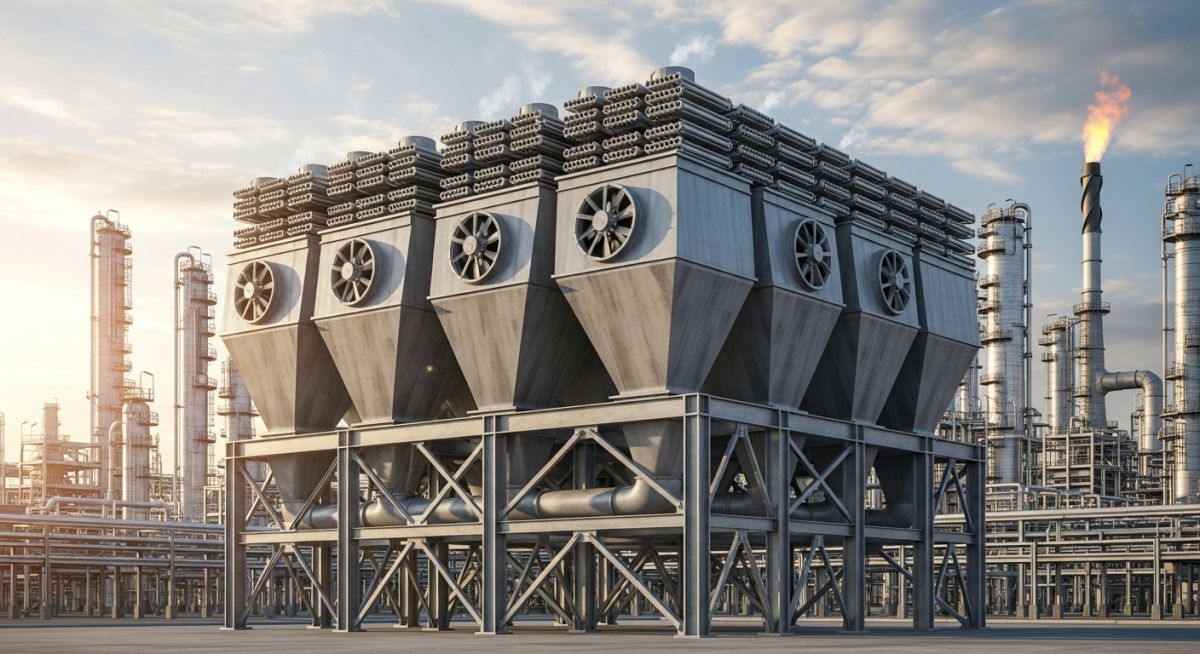
Over my 20 years in piping and process plant design, I have seen many engineers treat Air Cooled Heat Exchangers (ACHE)—or “fin-fans” as we call them in the field—as simple, self-contained packages. This is a costly mistake. An ACHE is a complex interaction of thermodynamics, structural dynamics, and piping stress. When you are routing a 24-inch overhead line from a distillation column to an ACHE inlet manifold, a single miscalculation in thermal expansion can warp the tube bundle or crack the nozzle welds. In my experience, understanding how these units behave under real-world operating conditions is what separates a reliable plant from one plagued by constant shutdowns.
- Understand the critical mechanical differences between forced and induced draft configurations.
- Learn how to calculate thermal expansion and manage nozzle loads using API Standard 661 guidelines.
- Identify the correct fin type based on operating temperature and environmental exposure.
- Implement a robust pre-commissioning checklist to prevent premature tube-to-tubesheet joint failures.
- Discover field-proven piping layouts that minimize stress on header boxes.
How Air Cooled Heat Exchangers Manage Thermal Stress
In my work on high-temperature refinery units, thermal expansion is the primary cause of mechanical failure in fin-fan exchangers. Because the tubes are exposed to hot process fluid while the supporting steel structure remains close to ambient temperature, a significant differential expansion occurs. If this expansion is restricted, the resulting compressive stress will cause the tubes to buckle or pull out of the tubesheet.
Forced Draft vs. Induced Draft Configurations
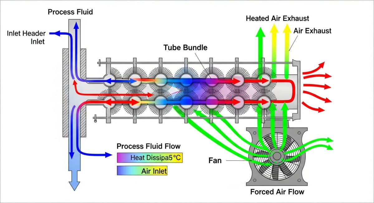
Choosing between forced and induced draft is the first major decision in any ACHE design. In a forced draft unit, the fans are located below the tube bundle. This makes maintenance easier because the drive assembly is close to the ground, and it keeps the fan blades out of the hot exhaust air stream. However, forced draft units suffer from poor air distribution across the bundle and are highly susceptible to hot air recirculation, where the warm exhaust air is drawn back into the fan intake.
Induced draft units have the fans located above the tube bundle. This pulls air through the bundle, resulting in highly uniform air distribution and much lower recirculation rates. The trade-off is that the fan components must be rated for the high exit air temperature, and maintenance requires working at elevation.
Finned Tube Heat Transfer Calculations
To calculate the required heat transfer area, we use the fundamental heat transfer equation:
Where:
- Q = Heat duty (Watts)
- U = Overall heat transfer coefficient based on bare tube area (W/m²·°C)
- A = Total bare tube surface area (m²)
- dT_lm = Logarithmic mean temperature difference (°C)
- F = LMTD correction factor for cross-flow configuration
Because air has a very low heat transfer coefficient compared to most process fluids, we use fins to increase the external surface area. The ratio of the external finned surface area to the internal bare tube surface area (known as the area ratio) typically ranges from 15 to 25.
To calculate the linear thermal expansion of the tubes, use the following formula:
Where dL is the expansion in millimeters, L is the tube length, alpha is the mean coefficient of thermal expansion of the tube material, T_op is the operating temperature, and T_amb is the ambient installation temperature. This expansion must be accommodated by allowing the header boxes to slide on low-friction Teflon or bronze slide plates, a requirement specified in ASME Section VIII Division 1.
Engineering Specifications for Air Cooled Heat Exchangers
In my experience, selecting the wrong fin type for high-temperature service leads to rapid mechanical degradation. The table below outlines the standard fin types used in industrial applications, their temperature limits, and their mechanical characteristics.
| Fin Type | Manufacturing Method | Max Temp (°C) | Heat Transfer Efficiency | Atmospheric Protection |
|---|---|---|---|---|
| L-Foot (Wrap-On) | Tension wound L-shaped aluminum strip | 120 | Moderate | Poor (moisture can penetrate foot) |
| Overlapped L-Foot (LL) | Double-folded L-shape covering entire tube | 170 | Good | Excellent (full tube coverage) |
| Embedded (G-Grooved) | Fin wound into mechanically plowed groove | 400 | Excellent | Moderate (groove must be sealed) |
| Extruded (Double Tube) | Outer aluminum tube extruded over inner tube | 300 | Outstanding | Outstanding (complete barrier) |
Technical Mapping & Specifications Matrix
To ensure compliance with international standards, the following matrix maps the core technical entities of an ACHE to their governing codes and design significance.
| Component / Parameter | Acronym / Symbol | Governing Standard | Design Significance |
|---|---|---|---|
| Header Box Design | HB | ASME Sec VIII Div 1 | Determines plate thickness and plug sheet spacing to withstand internal pressure. |
| Nozzle Load Limits | F_x, M_y | API Standard 661 | Defines maximum allowable forces and moments on header nozzles. |
| Vibration Limits | V_lim | ISO 10816 / API 661 | Prevents structural fatigue of the fan deck and tube-to-tubesheet joints. |
| Air Flow Rate | ACFM | ASHRAE / API 661 | Governs fan motor horsepower and noise emission levels. |
Site Inspection Checklist for Air Cooled Heat Exchangers
During the pre-commissioning phase of a project, I have often found critical installation errors that would have led to immediate equipment damage if left uncorrected. The following checklist must be executed by the field engineering team before any hot medium is introduced into the exchanger.
-
Slide Plate Clearance: Verify that the sliding header box is free to move on its Teflon/bronze slide plates. Ensure that shipping bolts have been removed and that piping loads do not bind the sliding mechanism.
-
Fan Blade Pitch Angle: Measure the pitch angle of every fan blade using a digital protractor. The variation between blades on a single fan hub must not exceed 0.5 degrees to prevent severe dynamic imbalance.
-
Belt Tension and Alignment: For V-belt driven units, check belt tension using a deflection force gauge. Verify pulley alignment using a laser alignment tool to prevent premature belt wear and power loss.
-
Nozzle Load Verification: Review the final piping stress analysis report. Ensure that actual cold-spring or piping alignment matches the design assumptions and that nozzle loads are well within API Standard 661 limits.
-
Louvers Operation: Manually cycle the inlet/outlet louvers through their full range of motion. Verify that the actuator stroke matches the louver blade rotation (0 to 90 degrees) and that there is no binding.
Field Case Study: Real-World Application
In a Middle Eastern gas processing plant, a newly commissioned overhead condenser ACHE experienced severe vibration and repeated tube-to-tubesheet joint leaks within three months of startup. The vibration levels on the fan deck exceeded 12 mm/s, far above the ISO limit of 4.5 mm/s. The plant operator suspected a structural design flaw in the steel support frame and was preparing for an expensive structural reinforcement shutdown.
I was called to the site to investigate. Instead of looking only at the steel frame, I analyzed the piping manifold and the fan assembly. We discovered two distinct issues:
- The 30-inch inlet manifold was rigidly anchored close to the exchanger, preventing the sliding header box from moving. This caused a massive thermal thrust force that warped the tube bundle.
- Two fan blades on Fan B had a pitch angle deviation of 1.8 degrees relative to the other blades, creating a severe aerodynamic imbalance.
We modified the piping support to allow the header box to slide freely and re-pitched the fan blades to within 0.3 degrees of each other. Upon restarting, vibration levels dropped to 2.1 mm/s, and the tube joint leaks stopped completely.
Direct Recommendation: Always perform a combined piping flexibility and structural dynamic analysis during the detailed engineering phase. Never assume that the piping stress engineer and the structural engineer can work in isolation.
Frequently Asked Engineering Questions
What is the maximum allowable noise level for industrial ACHEs?
How do you prevent winterization or freezing in cold climates?
Why is the LMTD correction factor (F) lower for ACHEs than shell and tube exchangers?
When should you choose plug headers over cover-plate headers?
How does ambient air temperature affect ACHE performance?
What is the purpose of a vibration cutout switch on an ACHE?
===
Complete Course on
Piping Engineering
Check Now
Key Features
- 125+ Hours Content
- 500+ Recorded Lectures
- 20+ Years Exp.
- Lifetime Access
Coverage
- Codes & Standards
- Layouts & Design
- Material Eng.
- Stress Analysis

📚 Recommended Resources: Air Cooled Heat Exchangers
Read these Guides


Related posts:
![3D render of a protective chromium oxide film forming on a stainless steel surface.]()
How Does Stainless Steel Oxide Film Formation Prevent Corrosion?
![Side-by-side comparison of industrial metal casting and metal forging processes.]()
Casting vs Forging: Key Differences for Industrial Piping Systems
![Various types of industrial pumps displayed in a modern engineering facility.]()
Guide to Types of Pumps and Their Working Principles
![3D digital GIS map overlay showing petroleum pipeline routes across a terrain]()
Why GIS in Petroleum and Pipeline Industry is Absolutely Critical
![CAESAR II Version 14 pipe stress analysis software interface displaying a 3D piping model.]()
What Is New in CAESAR II Version 14 Pipe Stress Analysis
![Cutaway 3D render of an industrial multi-stage centrifugal compressor showing internal impellers and volute casing.]()
Centrifugal Compressors: Engineering Design Guidelines and Industrial Applications