
Understanding Newton’s Law of Viscosity and Key Fluid Flow Factors
In my 20 years of designing piping systems and troubleshooting fluid transport lines, I have seen many young engineers make the mistake of treating every fluid like water. When you are dealing with heavy crude oil, polymer solutions, or high-pressure chemical lines, ignoring how a fluid deforms under shear can lead to catastrophic pump failures, ruptured lines, and massive pressure drops. Viscosity is not just a theoretical number in a textbook; it is the single most critical physical property that dictates how your pumps, valves, and pipes will behave in the field.
Whether you are sizing a centrifugal pump under API 610 guidelines or calculating line losses for a refinery expansion, you must understand how viscosity changes with temperature, pressure, and shear rate. Let us break down the core mechanics of fluid resistance, explore the factors that alter fluid behavior, and master the application of Newton’s law of viscosity in real-world engineering scenarios.
- The physical definition of dynamic and kinematic viscosity and how to convert between them.
- How temperature and pressure affect the viscosity of liquids versus gases.
- The mathematical formulation of Newton’s law of viscosity and its practical limits.
- How to distinguish between Newtonian and Non-Newtonian fluids in piping design.
- Real-world field calculations and troubleshooting strategies for highly viscous systems.
How Does Newton’s Law of Viscosity Govern Fluids?
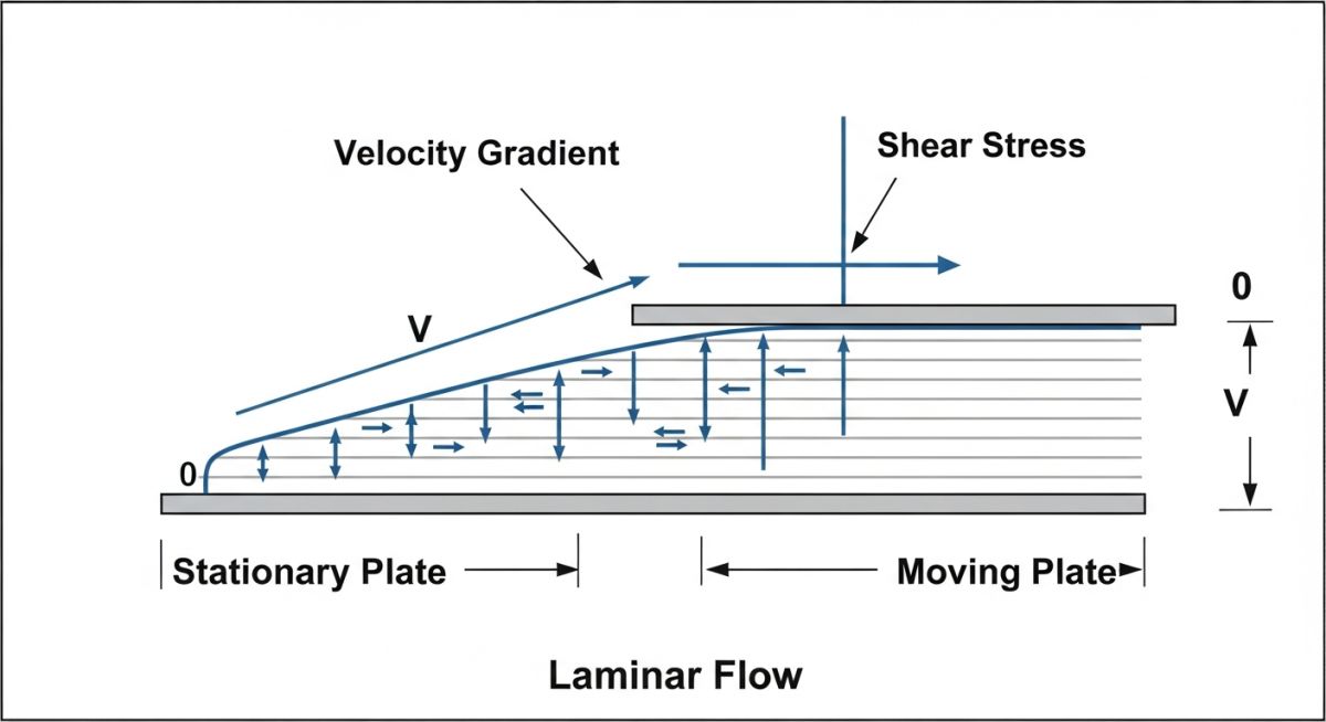
To understand how fluids behave inside a pipe, we must look at the molecular level. When a fluid flows, adjacent layers slide past one another. The friction between these layers is what we call viscosity. Isaac Newton formulated this relationship by observing fluid trapped between two parallel plates—one stationary and one moving at a constant velocity.
According to Newton’s law of viscosity, the shear stress (represented by the Greek letter tau) is directly proportional to the rate of shear strain (the velocity gradient, du/dy). Mathematically, we write this as:
Where:
- Shear Stress (tau): The force applied per unit area parallel to the fluid layers, measured in Pascals (Pa) or Newtons per square meter.
- Dynamic Viscosity (mu): The proportionality constant representing the fluid’s internal resistance, measured in Pascal-seconds (Pa-s) or Centipoise (cP).
- Velocity Gradient (du/dy): The change in velocity (du) over the distance between layers (dy), measured in reciprocal seconds (1/s). This is also known as the shear rate.
Dynamic vs. Kinematic Viscosity
In my design work, I constantly see engineers confuse dynamic viscosity with kinematic viscosity. Dynamic (or absolute) viscosity measures a fluid’s internal resistance to flow under an external force. Kinematic viscosity (represented by the Greek letter nu) is the ratio of dynamic viscosity to the fluid’s density (rho):
Kinematic viscosity represents how fast a fluid spreads or flows under the influence of gravity alone. Its SI unit is square meters per second (m^2/s), but in the field, we almost always use Centistokes (cSt), where 1 cSt equals 1 square millimeter per second.
In heavy fuel oil (HFO) transfer lines, a drop in temperature of just 10 degrees Celsius can cause the viscosity to spike by over 300 percent. If your heat tracing system fails, your transfer pumps will lock up due to high torque demand. Always design your piping systems for the worst-case minimum operating temperature, not just the nominal process temperature.
Factors Affecting Fluid Viscosity
Viscosity is not a static property. It changes dynamically based on several environmental and physical factors:
- Temperature: This is the most dominant factor. In liquids, cohesive forces between molecules decrease as temperature rises, causing viscosity to drop. In gases, molecular collisions increase with temperature, which actually increases gas viscosity.
- Pressure: For most liquids, viscosity is relatively independent of pressure at low to moderate ranges. However, at extreme pressures (such as in deep-well oil extraction or high-pressure hydraulics), liquid molecules are compressed closer together, increasing cohesive forces and raising viscosity. For gases, viscosity increases directly with high pressures.
- Shear Rate: For Newtonian fluids, viscosity remains constant regardless of the shear rate. For Non-Newtonian fluids, viscosity can decrease (shear-thinning/pseudoplastic) or increase (shear-thickening/dilatant) as the shear rate increases.
The table below provides typical dynamic and kinematic viscosity values for common industrial fluids at standard atmospheric pressure. These values are critical when performing line sizing calculations under ASME B31.3.
| Fluid Name | Temperature (C) | Dynamic Viscosity (cP) | Density (kg/m^3) | Kinematic Viscosity (cSt) | Flow Behavior |
|---|---|---|---|---|---|
| Water | 20 | 1.00 | 998.2 | 1.00 | Newtonian |
| Water | 80 | 0.35 | 971.8 | 0.36 | Newtonian |
| Lube Oil (SAE 30) | 20 | 290.00 | 890.0 | 325.80 | Newtonian |
| Glycerin | 20 | 1490.00 | 1261.0 | 1181.60 | Newtonian |
| Heavy Crude Oil | 15 | 450.00 | 920.0 | 489.10 | Non-Newtonian (Shear-Thinning) |
This matrix maps fluid properties to their corresponding testing standards and engineering applications. Use this to select the correct testing protocol for your project specifications.
| Property / Parameter | Standard Reference | Primary Measurement Device | Engineering Application |
|---|---|---|---|
| Kinematic Viscosity | ASTM D445 / ISO 3104 | Glass Capillary Viscometer | Piping pressure drop, Reynolds number calculations |
| Dynamic Viscosity | ASTM D2196 | Rotational Viscometer (Brookfield) | Pump shaft power, agitator torque sizing |
| High-Shear Viscosity | ASTM D4683 | Tapered Bearing Simulator | Engine oil lubrication, high-speed bearing design |
| Viscosity Index (VI) | ASTM D2270 | Calculated from ASTM D445 data | Lubricant selection for wide temperature ranges |
Applying Newton’s Law of Viscosity in Design
Before finalizing any piping isometric or pump datasheet, you must verify that your fluid properties match the actual field operating conditions. Use this checklist during the detailed engineering phase to prevent costly field modifications.
-
Verify Fluid Classification: Confirm if the fluid is Newtonian or Non-Newtonian. If Non-Newtonian, obtain the shear-rate vs. viscosity curve from the lab. -
Check Minimum Ambient Temperature: Ensure the piping heat tracing system is sized to maintain the fluid viscosity below the maximum limit of the pump. -
Calculate Reynolds Number at Worst Case: Use the highest viscosity (at lowest operating temperature) to verify if the flow is laminar, transitional, or turbulent. -
Size Pump for Viscous Derating: Apply the Hydraulic Institute (HI) viscosity correction factors if using a centrifugal pump for fluids above 10 cSt. -
Review Valve Pressure Drops: Ensure control valves are sized using the correct viscosity correction factors to prevent cavitation and flashing. -
Confirm Lab Test Standards: Verify that the viscosity values on the process datasheet were measured using ASTM D445 or equivalent standards. -
Validate Pipe Wall Shear Stress: Ensure the calculated wall shear stress does not exceed the erosion-corrosion limits of the selected pipe material.
Field Case Study: Real-World Application
Direct Recommendation: Never assume your process fluid will always remain at its design temperature. Always perform a sensitivity analysis on your viscosity values. If your fluid is highly temperature-sensitive, insulate your lines and consider positive displacement pumps instead of centrifugal pumps.
Frequently Asked Engineering Questions
What is the difference between Newtonian and Non-Newtonian fluids?
How does temperature affect gas viscosity compared to liquid viscosity?
Why is kinematic viscosity used more often in piping design than dynamic viscosity?
What are the units of viscosity in the SI and Imperial systems?
How does high viscosity affect centrifugal pump performance?
What is the Viscosity Index (VI) and why does it matter?
Complete Course on
Piping Engineering
Check Now
Key Features
- 125+ Hours Content
- 500+ Recorded Lectures
- 20+ Years Exp.
- Lifetime Access
Coverage
- Codes & Standards
- Layouts & Design
- Material Eng.
- Stress Analysis
