Table of Contents

How to Calculate Pipe Support Spacing for Industrial Piping Systems
In my 20 plus years of executing piping stress analysis for heavy industrial plants, I have seen many field failures that trace back to a single, fundamental mistake: incorrect support placement. When a pipeline is allowed to sag beyond its design limits, it does not just look unprofessional; it pools condensate, creates localized stress concentrations, and invites catastrophic water hammer. Determining the correct distance between supports is a balancing act between structural mechanics, thermal flexibility, and project economics.
Throughout my career, I have learned that relying solely on generic tables without understanding the underlying physics is a recipe for disaster. Whether you are routing a high-temperature steam line or a heavy slurry header, you must evaluate the specific weight of the pipe, the fluid, the insulation, and the potential environmental loads. Let us break down the exact engineering principles, formulas, and code requirements that govern this critical design step.
Key Engineering Takeaways
- Learn the exact mathematical formulas for calculating bending stress and deflection limits.
- Understand how to apply standard span charts while accounting for insulation and fluid weight.
- Discover the critical differences between gas-filled and liquid-filled piping span designs.
- Access a field-tested verification checklist to ensure your physical installations match your stress models.
Why Pipe Support Spacing Matters in Design
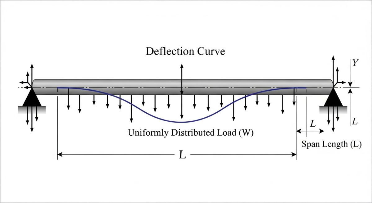
When we design a piping system, we treat the pipe as a continuous beam supported at multiple points. The spacing between these supports directly dictates the bending stress and the deflection of the pipe. If the supports are too far apart, the pipe sags. This sag, or deflection, creates low points where liquid can accumulate. In steam systems, this pooled condensate leads to steam hammer, which can rupture valves and fittings.
To prevent these issues, we design within strict limits defined by codes like ASME B31.3 for process piping and ASME B31.1 for power piping. These codes require that the longitudinal stresses due to sustained loads (pressure, weight of pipe, contents, and insulation) do not exceed the allowable stress of the material at the operating temperature.
The Governing Mathematical Formulas
To calculate the maximum allowable span, we must evaluate two primary structural criteria: bending stress and deflection.
1. Bending Stress Criterion
For a continuous beam with uniform load distribution, the maximum bending stress is calculated using the following relationship:
S = (w * L^2) / (8 * Z)
Where:
S = Bending stress (psi or MPa)
w = Total weight per unit length of the pipe, including fluid and insulation (lb/in or N/mm)
L = Span length between supports (in or mm)
Z = Section modulus of the pipe cross-section (in^3 or mm^3)
2. Deflection Criterion
In my practice, I limit the maximum deflection of the pipe to 0.1 inches (2.5 mm) for industrial process lines, or 1/360th of the span length, whichever is smaller. The deflection formula for a continuous beam is:
y = (w * L^4) / (384 * E * I)
Where:
y = Maximum deflection (in or mm)
E = Modulus of elasticity of the pipe material at operating temperature (psi or MPa)
I = Moment of inertia of the pipe cross-section (in^4 or mm^4)
Always calculate your support spans based on the pipe filled with water for hydrotesting, even if the operating fluid is a light gas. I have witnessed structural steel supports buckle during pre-commissioning because the designer calculated the span based on the light operating weight of nitrogen gas rather than the heavy weight of water during the hydrotest phase.
Adjusting Spans for Concentrated Loads
The standard formulas assume a uniformly distributed load. However, real-world piping systems are loaded with heavy inline components like valves, strainers, flanges, and instruments. These concentrated loads act as point loads, which drastically increase the local bending moment and deflection.
When a heavy valve is placed in a span, the allowable span length must be reduced. A common rule of thumb in piping design is to place a support as close as possible to any heavy inline valve or instrument, ideally within a distance of three to five times the pipe diameter. This isolates the heavy component and prevents it from inducing excessive bending stresses on the adjacent pipe runs.
Standard Pipe Support Spacing Chart for Carbon Steel
The table below provides the maximum recommended pipe support spacing for standard weight (Schedule 40) carbon steel pipes filled with water or steam. These values are based on a maximum deflection limit of 0.1 inches (2.5 mm) and a maximum bending stress of 2,300 psi, which is highly conservative and safe for most industrial applications.
| Nominal Pipe Size (NPS) | Outside Diameter (in) | Water Service Span (ft) | Water Service Span (m) | Steam/Gas Span (ft) | Steam/Gas Span (m) |
|---|---|---|---|---|---|
| 1″ | 1.315 | 7.0 | 2.1 | 9.0 | 2.7 |
| 2″ | 2.375 | 10.0 | 3.0 | 13.0 | 4.0 |
| 3″ | 3.500 | 12.0 | 3.7 | 15.0 | 4.6 |
| 4″ | 4.500 | 14.0 | 4.3 | 17.0 | 5.2 |
| 6″ | 6.625 | 17.0 | 5.2 | 21.0 | 6.4 |
| 8″ | 8.625 | 19.0 | 5.8 | 24.0 | 7.3 |
| 12″ | 12.750 | 23.0 | 7.0 | 30.0 | 9.1 |
Technical Mapping and Support Specifications Matrix
Different piping materials and operating conditions require distinct support strategies. The matrix below maps out the relationship between material grades, temperature ranges, and the recommended support configurations to prevent structural failure.
| Material Grade | Temperature Range | Primary Support Type | Code Reference | Design Margin Factor |
|---|---|---|---|---|
| ASTM A106 Gr. B | -20 to 650 deg F | Rigid Shoe / Hanger | ASME B31.3 | 1.20 |
| ASTM A312 TP316 | -320 to 1000 deg F | Spring Hanger / Slide Plate | ASME B31.3 | 1.25 |
| Chrome-Moly (P22) | 700 to 1100 deg F | Constant Effort Hanger | ASME B31.1 | 1.30 |
| FRP / GRP | Ambient to 200 deg F | Saddles / Wide Band Clamps | AWWA M45 | 1.50 |
Field Verification Checklist for Pipe Spans
Even the most precise stress analysis is useless if the field installation does not match the design. Over my career, I have developed this checklist to help field engineers verify support spans before the system is pressurized or hydrotested.
Pre-Commissioning Span Checklist
-
Verify Actual Span Lengths: Measure the physical distance between support centers. Ensure they do not exceed the maximum values specified on the isometric drawings by more than 5 percent.
-
Inspect Concentrated Load Supports: Confirm that heavy inline components (valves, strainers, flow meters) have dedicated supports located within three pipe diameters of the component flange.
-
Check Support Clearance and Travel: For hot lines, verify that the pipe shoes have sufficient clearance on the structural steel to slide during thermal expansion without falling off the beam.
-
Evaluate Spring Hanger Presets: Ensure all variable and constant spring hangers have their travel stops removed and are set to their cold load positions before hydrotesting.
-
Assess Slope and Drainage: Verify that the line maintains its designed slope (e.g., 1:100 for steam lines) across all spans to prevent condensate pooling and subsequent water hammer.
Field Case Study: Real-World Application
The Problem: Severe Vibration in a 12-Inch Cooling Water Line
During the commissioning of a petrochemical plant expansion, a 12-inch cooling water header experienced severe, low-frequency vibrations. The vibration was so intense that it caused the structural steel support frames to shake, threatening the integrity of nearby instrument connections. The original design had utilized a standard span chart that assumed a maximum span of 23 feet between supports. However, the designer failed to account for a heavy control valve station located right in the middle of one of the spans, which added over 1,200 pounds of concentrated weight.
The Outcome: Re-Engineering and Span Reduction
I was brought in to perform a field audit and stress analysis. We modeled the system in CAESAR II and found that the bending stress at the valve location exceeded the ASME B31.3 allowable limit by 45 percent, and the local deflection was 0.45 inches—well over the 0.1-inch limit. To resolve this, we added a dedicated rigid support directly beneath the control valve assembly and introduced an intermediate guide support 10 feet upstream. This reduced the effective span to 12 feet in the critical zone. Upon restarting the pumps, the vibration was completely eliminated, and the deflection dropped to a safe 0.05 inches.
This case study highlights the danger of relying blindly on standard span charts. Always look at the physical layout and identify concentrated loads that require localized support modifications.
Frequently Asked Engineering Questions
How does insulation weight affect the maximum pipe support span?
What is the maximum allowable deflection for industrial piping?
Can I use the same span spacing for carbon steel and stainless steel pipes?
How do wind and seismic loads impact pipe support spacing?
Why are steam line support spans different from water line spans?
What code governs the design of pipe supports and spans?
===FAQ_BLOCK===
Complete Course on
Piping Engineering
Check Now
Key Features
- 125+ Hours Content
- 500+ Recorded Lectures
- 20+ Years Exp.
- Lifetime Access
Coverage
- Codes & Standards
- Layouts & Design
- Material Eng.
- Stress Analysis

📚 Recommended Resources: pipe support spacing
Read these Guides
🎓 Advanced Training


Related posts:
![A mechanical sucker rod pumpjack operating in an oil field at sunset]()
What is Sucker Rod Pump System in Oil Production?
![Piping material engineer reviewing technical specifications on a tablet in an industrial plant.]()
How a Piping Material Engineer Drives Industrial Project Success
![Industrial refinery plant showing various types of static equipment]()
What is Static Equipment? Types and List of Static Equipments
![Side-by-side comparison of industrial process piping and power plant steam piping systems.]()
Differences Between ASME B31.3 and B31.1: B31.3 vs B31.1
![Large industrial steel storage tank under construction with cranes and scaffolding]()
Storage Tank Construction Method Statement: Step-by-Step Engineering Guide
![Cutaway diagram of a globe control valve highlighting the internal valve trim components]()
What is a Valve Trim? Types, Components, and Selection


