Table of Contents
What is Fire Point and the Difference Between Flash Point and Fire Point
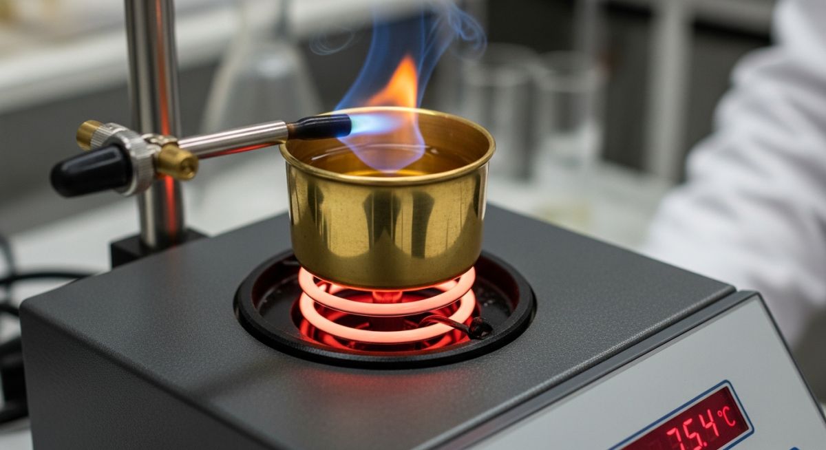
In my 20-plus years of designing piping systems and process plants for high-temperature refineries, I have seen how a simple misunderstanding of fluid properties can lead to catastrophic field failures. Many junior engineers I mentor often confuse flash point with fire point, assuming that if a fluid is kept below its fire point, it is completely safe from ignition. This is a dangerous misconception.
When you are routing high-pressure lube oil lines near steam pipes or designing storage tanks for volatile hydrocarbons, knowing the exact thermal thresholds of your process fluids is not just academic—it is a fundamental safety requirement. Let us break down these thermodynamic properties from a practical, boots-on-the-ground engineering perspective.
Key Takeaways for Piping & Process Engineers
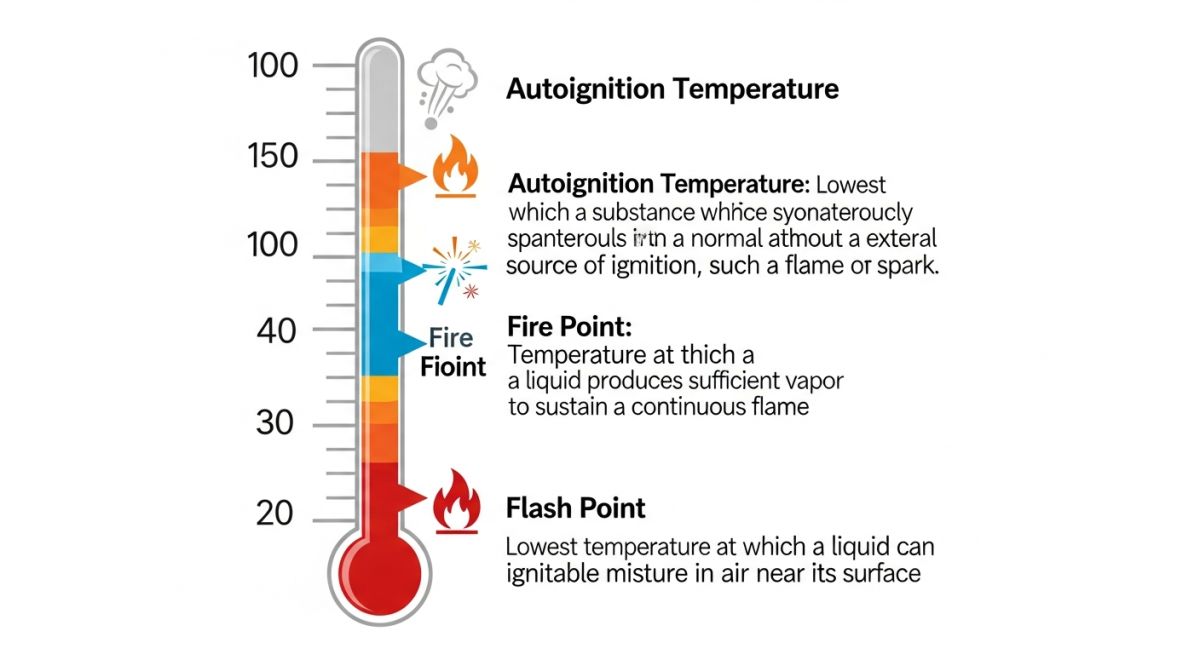
- The flash point indicates the initiation of transient ignition, while the fire point marks the threshold for sustained combustion.
- The fire point is always higher than the flash point, typically by a margin of 5°C to 30°C for most industrial hydrocarbons.
- Closed-cup testing (ASTM D93) yields lower, more conservative flash points compared to open-cup testing (ASTM D92).
- Piping designs must maintain operating temperatures well below the flash point, or implement strict hazardous area classification and mitigation measures.
Complete Course on
Piping Engineering
Check Now
Key Features
- 125+ Hours Content
- 500+ Recorded Lectures
- 20+ Years Exp.
- Lifetime Access
Coverage
- Codes & Standards
- Layouts & Design
- Material Eng.
- Stress Analysis
Explaining the Difference Between Flash Point and Fire Point
Thermal Ignition Thresholds: The difference between flash point and fire point represents the thermal energy gap required to transition from transient ignition to sustained combustion. This temperature interval typically ranges from 5 to 30 degrees Celsius depending on the molecular weight and vapor pressure of the specific hydrocarbon fluid.
To understand why this gap exists, we must look at the physical chemistry of vaporization. For a liquid to burn, it must first vaporize. The vapor mixes with oxygen in the air to form a combustible mixture.
The Physics of the Flash Point
At the flash point, the liquid has reached a temperature where its vapor pressure is high enough to produce a vapor concentration equal to the Lower Flammability Limit (LFL) near the surface. When we introduce an ignition source, this pocket of vapor ignites. However, because the bulk liquid temperature is still relatively low, the rate of vaporization cannot keep up with the rate of combustion. The flame consumes the available vapor and immediately goes out.
The Physics of the Fire Point
As we continue to heat the liquid, we reach the fire point. At this elevated temperature, the rate of vaporization is high enough to continuously supply fuel to the flame front. The heat radiated back from the flame to the liquid surface further accelerates vaporization, creating a self-sustaining combustion loop that lasts for at least five seconds.
In my career, I have seen engineers specify piping insulation based on open-cup flash points, only to suffer leaks that ignited at lower temperatures. Closed-cup tests (like ASTM D93) prevent vapor escape, simulating a confined space like a pipe gallery or valve box. Always use closed-cup data for piping design safety margins, as open-cup values can be 10% to 20% higher, giving a false sense of security.
Engineering Calculation: Estimating Vapor Pressure at Flash Point
We can estimate the vapor pressure of a pure fluid at its flash point using the Antoine Equation. This helps us verify if a fluid is operating near its flammability limits.
Antoine Equation:
log10(P) = A – [B / (T + C)]
Where:
– P = Vapor pressure (mmHg)
– T = Temperature (°C)
– A, B, C = Component-specific Antoine constants
Let us calculate the vapor pressure of Ethanol at its closed-cup flash point of 13°C. The Antoine constants for Ethanol are:
– A = 8.20417
– B = 1642.89
– C = 230.30
Step 1: Substitute T = 13°C into the equation:
log10(P) = 8.20417 – [1642.89 / (13 + 230.30)]
log10(P) = 8.20417 – [1642.89 / 243.30]
log10(P) = 8.20417 – 6.75253
log10(P) = 1.45164
Step 2: Solve for P:
P = 10^(1.45164) ≈ 28.29 mmHg
This calculated vapor pressure (28.29 mmHg) at 13°C represents the exact pressure required to generate a concentration of ethanol vapor in air that matches its Lower Flammability Limit (approximately 3.3% by volume at atmospheric pressure). If your piping system operates above 13°C, any leak will immediately form an ignitable mixture.
The table below outlines the typical flash and fire points for common industrial fluids. These values are critical when designing heat exchangers, lube oil consoles, and fuel piping networks.
| Fluid Name | Flash Point (°C) | Fire Point (°C) | ASTM Standard | Piping Design Consideration |
|---|---|---|---|---|
| ISO VG 46 Lube Oil | 210°C (Open) | 235°C (Open) | ASTM D92 | Keep piping away from steam lines >200°C. |
| Diesel Fuel (No. 2) | 52°C (Closed) | 62°C (Open) | ASTM D93 | Class II combustible liquid; requires explosion-proof fittings. |
| Turbine Oil (ISO VG 32) | 215°C (Open) | 240°C (Open) | ASTM D92 | High-pressure spray leaks can ignite below flash point. |
| Ethanol (95%) | 13°C (Closed) | 17°C (Open) | ASTM D93 | Class IB flammable liquid; requires strict grounding/bonding. |
| Ethylene Glycol | 111°C (Closed) | 121°C (Open) | ASTM D93 | Low volatility, but thermal degradation lowers flash point. |
This matrix maps the core thermodynamic parameters to their physical significance and relevant international standards.
| Parameter | Acronym / Symbol | Physical Significance | Standard Reference |
|---|---|---|---|
| Flash Point | FP / T_flash | Lowest temp for transient ignition (vapor concentration reaches LFL). | NFPA 30 / ASTM D93 |
| Fire Point | T_fire | Lowest temp where vaporization rate sustains combustion for >= 5 seconds. | ASTM D92 |
| Autoignition Temperature | AIT / T_auto | Temperature at which fluid ignites spontaneously without an external spark. | ASTM E659 |
| Lower Flammability Limit | LFL / LEL | Minimum concentration of fuel vapor in air that can propagate a flame. | ASTM E681 |
Verifying Thermal Safety in Piping Designs
Thermal Safety Verification: Piping design verification requires systematic validation of fluid operating temperatures against established flash and fire points to eliminate ignition risks. This process ensures compliance with ASME B31.3 and NFPA 30 codes through rigorous thermal insulation and ventilation audits.
When conducting a design review or a walkdown of an operating unit, use this checklist to ensure that the gap between operating temperatures and fluid ignition thresholds is safely managed.
Piping Thermal Safety Audit Checklist
-
Verify Fluid Operating Temperature: Ensure the maximum operating temperature of the fluid is at least 15°C below its closed-cup flash point. If this is not possible, classify the area per API RP 500.
-
Audit High-Pressure Spray Hazards: Identify any high-pressure lines (e.g., hydraulic systems operating >10 bar) carrying fluids near hot surfaces. High-pressure sprays can atomize and ignite even if the bulk fluid temperature is below the flash point.
-
Inspect Thermal Insulation (Cladding): Verify that hot piping (such as steam or hot utility oil lines) is fully insulated and clad to prevent leaked process fluids from contacting surfaces above their fire points.
-
Check Double-Containment Specifications: For piping carrying fluids above their flash points through confined spaces or corridors, specify double-walled piping with continuous leak detection.
-
Review Vent and Drain Routing: Ensure all atmospheric vents and drains from vessels containing fluids near their flash points are routed to a safe location (e.g., flare header or slop system) rather than local atmosphere.
Field Case Study: Real-World Application
During a commissioning phase at a combined-cycle power plant, a high-pressure lube oil line feeding a steam turbine bearing developed a pinhole leak at a socket-welded fitting. The lube oil (ISO VG 46) was operating at 65°C, well below its flash point of 210°C. However, the high-pressure spray (12 bar) atomized the oil into a fine mist. This mist drifted onto an uninsulated section of a high-pressure steam pipe operating at 420°C. Because the local surface temperature was far above the oil’s fire point (235°C) and autoignition temperature (320°C), the mist immediately flashed and sustained a violent, continuous fire that damaged nearby instrument cabling.
As the lead piping consultant brought in to investigate, I implemented a three-pronged remediation strategy:
- Piping Redesign: Replaced all socket-welded fittings in the high-pressure lube oil system with butt-welded joints subjected to 100% volumetric radiography per ASME B31.3.
- Physical Shielding: Installed stainless steel spray shields around all mechanical joints and valves to prevent any future leaks from atomizing or spraying toward hot surfaces.
- Insulation Upgrade: Mandated that all steam piping within a 15-meter radius of the lube oil console be insulated and wrapped with aluminum cladding sealed with high-temperature silicone to prevent oil absorption into the insulation.
This incident highlights why we cannot rely solely on bulk fluid operating temperatures. Atomization completely changes the ignition dynamics, effectively bypassing the safety margin provided by a high flash or fire point.
Analyzing the Difference Between Flash Point and Fire Point
Thermal Safety Analysis: Analyzing the difference between flash point and fire point allows engineers to establish safe operating envelopes for high-temperature process piping. This analysis ensures that transient thermal excursions do not escalate into sustained industrial conflagrations.
Why is the fire point always higher than the flash point?
What is the typical temperature difference between flash and fire points?
Can a fluid ignite below its flash point?
How does ASTM D92 differ from ASTM D93?
What is the difference between flash point and autoignition temperature?
How does pressure affect the flash and fire points?
===

📚 Recommended Resources: difference between flash point and fire point
Related posts:
![A mechanical sucker rod pumpjack operating in an oil field at sunset]()
What is Sucker Rod Pump System in Oil Production?
![Piping material engineer reviewing technical specifications on a tablet in an industrial plant.]()
How a Piping Material Engineer Drives Industrial Project Success
![Industrial refinery plant showing various types of static equipment]()
What is Static Equipment? Types and List of Static Equipments
![Side-by-side comparison of industrial process piping and power plant steam piping systems.]()
Differences Between ASME B31.3 and B31.1: B31.3 vs B31.1
![Large industrial steel storage tank under construction with cranes and scaffolding]()
Storage Tank Construction Method Statement: Step-by-Step Engineering Guide
![Cutaway diagram of a globe control valve highlighting the internal valve trim components]()
What is a Valve Trim? Types, Components, and Selection


