Eliminating Centrifugal Pump Cavitation: The Definitive Engineering Manual
You hear it before you see it: a sound like gravel being churned inside your casing, followed by a sudden drop in discharge pressure and a spike in bearing vibration. In high-stakes industrial environments, Centrifugal Pump Cavitation isn’t just a maintenance nuisance—it is a catastrophic failure in progress that can eat through a 316 stainless steel impeller in weeks.
This guide moves beyond basic definitions to provide you with the exact hydraulic calculations, NPSH margin requirements, and forensic diagnostic steps needed to stabilize your system and extend MTBF (Mean Time Between Failure) across your entire pump fleet.
Key Engineering Takeaways
- Hydraulic Stability: How to maintain a minimum 10% NPSH margin to prevent vapor bubble formation.
- Damage Identification: Differentiating between classical cavitation pitting and recirculation-induced erosion.
- System Optimization: 2026 industry best practices for suction piping design and velocity control.
What is Centrifugal Pump Cavitation?
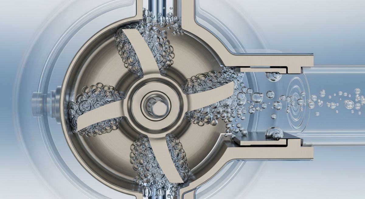
Centrifugal pump cavitation occurs when the local suction pressure drops below the fluid’s vapor pressure, causing vapor bubbles to form. As these bubbles move to higher-pressure zones near the impeller blades, they collapse violently, generating micro-jets and shockwaves that cause mechanical pitting, intense vibration, and significant loss of hydraulic efficiency.
Founder’s Insight: “In over two decades of commissioning API 610 pumps, I’ve found that 80% of cavitation issues are rooted in poor suction piping geometry, not the pump design itself. Always check your ‘Straight Run’ requirements before blaming the impeller.”
— Atul Singla
Complete Course on
Piping Engineering
Check Now
Key Features
- 125+ Hours Content
- 500+ Recorded Lectures
- 20+ Years Exp.
- Lifetime Access
Coverage
- Codes & Standards
- Layouts & Design
- Material Eng.
- Stress Analysis
Engineering Mastery: Cavitation Assessment
Validate your technical knowledge for 2026 certification standards
What physical event triggers the start of Centrifugal Pump Cavitation?
Technical Audit Complete!
You are ready to proceed to the core engineering fundamentals.
1. Understanding the Physics of Centrifugal Pump Cavitation
At its core, Centrifugal Pump Cavitation is a two-stage phase-change phenomenon governed by the relationship between local static pressure and the fluid's thermodynamic vapor pressure. When liquid enters the impeller eye, it must accelerate to match the vane velocity. According to Bernoulli’s principle, this increase in kinetic energy causes a simultaneous drop in pressure. If the pressure at any point—typically the suction side of the blade leading edge—falls below the vapor pressure (Pv) at the operating temperature, the liquid "boils" at room temperature, forming millions of microscopic vapor cavities.
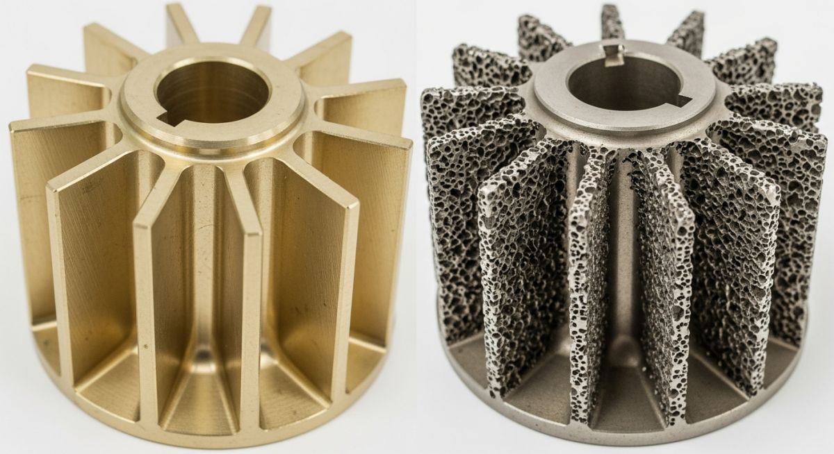
The secondary and most destructive phase occurs as these vapor bubbles are swept further into the impeller channels. As they move toward the higher-pressure discharge zones, the surrounding fluid pressure suddenly exceeds the internal bubble pressure, causing a violent, supersonic implosion. These implosions generate localized micro-jets with pressures reaching up to 100,000 PSI and temperatures exceeding 5,000°F. The cumulative impact of these shockwaves against the impeller surface causes "sponge-like" pitting and mechanical fatigue.
Standard Reference: ANSI/HI 9.6.1
"NPSH Margin is required because the industry standard definition of NPSHr (NPSH3) represents a condition where the pump has already lost 3% of its total head due to established cavitation."
View Hydraulic Institute GuidelinesEngineering for Centrifugal Pump Cavitation prevention requires a deep understanding of suction energy. High-suction energy pumps, often defined by their Suction Specific Speed (Nss), are significantly more susceptible to damage even at low levels of cavitation. Modern 2026 diagnostic protocols emphasize that cavitation inception (NPSHi) can occur at pressures 2 to 10 times higher than the manufacturer's quoted NPSHr, meaning "meeting the curve" is rarely enough for high-reliability assets.
2. The Critical Role of NPSH in Preventing Centrifugal Pump Cavitation
Net Positive Suction Head (NPSH) is the primary metric used to quantify the "safety buffer" between a liquid's current state and its boiling point at the pump suction. To eliminate Centrifugal Pump Cavitation, engineers must balance two distinct values: the system's "Available" head (NPSHa) and the pump's "Required" head (NPSHr). The former is a property of the system piping and tank elevation, while the latter is a mechanical constraint determined by the impeller's hydraulic design.
In the 2026 industrial landscape, relying on a simple NPSHa > NPSHr check is considered an outdated practice. Reliability engineers now utilize the NPSH Margin Ratio. For standard water service, a ratio of 1.1 (10% margin) is typically sufficient. However, for critical chemical or hydrocarbon services, API 610 and HI standards recommend a margin of 1.3 or higher. This accounts for transient system changes, such as fluid temperature spikes or gradual strainer clogging, which can quickly erode a slim pressure margin.
Calculating NPSHa requires precise field measurements. The formula NPSHa = Ha ± Hs - Hf - Hvp must account for:
- Ha: Absolute pressure on the liquid surface (Barometric pressure).
- Hs: Static head or lift from the liquid level to the pump centerline.
- Hf: Friction losses in the suction piping, including valves and strainers.
- Hvp: Vapor pressure of the liquid at the actual pumping temperature.
3. Identifying Early Warning Signs of Centrifugal Pump Cavitation
Detecting Centrifugal Pump Cavitation before metal loss occurs is critical for 2026 predictive maintenance programs. The most distinct hallmark is "broadband" high-frequency vibration. Unlike mechanical unbalance, which manifests at the 1X running speed, cavitation-induced energy typically resides in the 2 kHz to 20 kHz range. This "floor" of noise is caused by the random, high-velocity implosions of vapor bubbles hitting the internal casing walls.
Furthermore, engineers should monitor the Total Dynamic Head (TDH) vs. Power consumption ratio. In a cavitating state, the pump may maintain speed, but the discharge pressure will fluctuate wildly (surging), and the motor current (Amps) will drop. This occurs because the impeller is spinning in a mixture of liquid and vapor, which has a significantly lower density than the pure process fluid.
4. Engineering Solutions to Eliminate Centrifugal Pump Cavitation
Correcting Centrifugal Pump Cavitation requires adhering to rigorous standards like ASME B73.1 for chemical pumps or API 610 for refinery services. If NPSHa is insufficient, the first line of defense is optimizing the suction piping. This includes replacing standard elbows with long-radius versions and ensuring a minimum of five pipe diameters of straight run before the suction flange to prevent "pre-swirl" and turbulence.
In more severe cases, mechanical modifications are necessary. Installing an Inducer—a small axial-flow impeller upstream of the main impeller—can artificially boost the pressure at the suction eye. Alternatively, selecting a pump with a larger suction eye or lower Suction Specific Speed (Nss < 11,000) can broaden the stable operating window and significantly reduce the likelihood of vaporous cavitation.
| Solution Category | Method | Effect on Cavitation |
|---|---|---|
| System Change | Lower Pump Elevation | Increases NPSHa by increasing Static Head |
| Piping Fix | Increase Suction Pipe Size | Increases NPSHa by reducing Friction Losses |
| Mechanical Fix | Install Inducer | Reduces the pump's required NPSHr |
| Process Fix | Install Suction Cooler | Lowers Vapor Pressure (Pv) |
For detailed mechanical tolerances and allowable vibration limits during cavitation, consult the API 610 Standard for Centrifugal Pumps.
NPSHa & Margin Calculator (2026 Standards)
Calculate your system's Available NPSH and determine if you are at risk of Centrifugal Pump Cavitation.
Fill in the values to check for Centrifugal Pump Cavitation risk.
5. Case Study: Forensic Analysis of Centrifugal Pump Cavitation
The Case of the "Disappearing" Impeller Vanes
A large-scale municipal water plant reported a 15% drop in discharge flow on a high-service pump within just 4,000 hours of operation. Initial vibration analysis showed a significant "noise floor" elevation between 5 kHz and 12 kHz, classic markers for Centrifugal Pump Cavitation. Despite the suction pressure gauge reading 12 PSI (well above the vapor pressure), the damage was catastrophic.
The Root Cause
Forensic inspection of the suction piping revealed an un-vane elbow located directly at the pump suction flange. This created a high-velocity "jet" on one side of the impeller eye, causing local pressure to drop below vapor pressure even though the average suction pressure seemed safe.
The 2026 Solution
The plant installed a suction flow straightener and increased the pipe diameter from 10" to 12". This modification raised the NPSHa by 4.5 feet and eliminated the turbulent pre-swirl, completely stopping the cavitation-induced vibration.
Result: Following the repair and piping modification, the pump has operated for over 12,000 hours with zero loss in hydraulic efficiency and vibration levels remaining within ISO 10816-3 "Zone A" limits.
EPCLand YouTube Channel
2,500+ Videos • Daily Updates
Expert Insights: Lessons from 20 years in the field
-
Avoid the Suction Specific Speed Trap: Many engineers select pumps with high Nss (>11,000) to achieve lower NPSHr. However, these pumps often have a very narrow operating window. In 2026, we prioritize mechanical robustness over a lower NPSHr to ensure long-term resistance to Centrifugal Pump Cavitation.
-
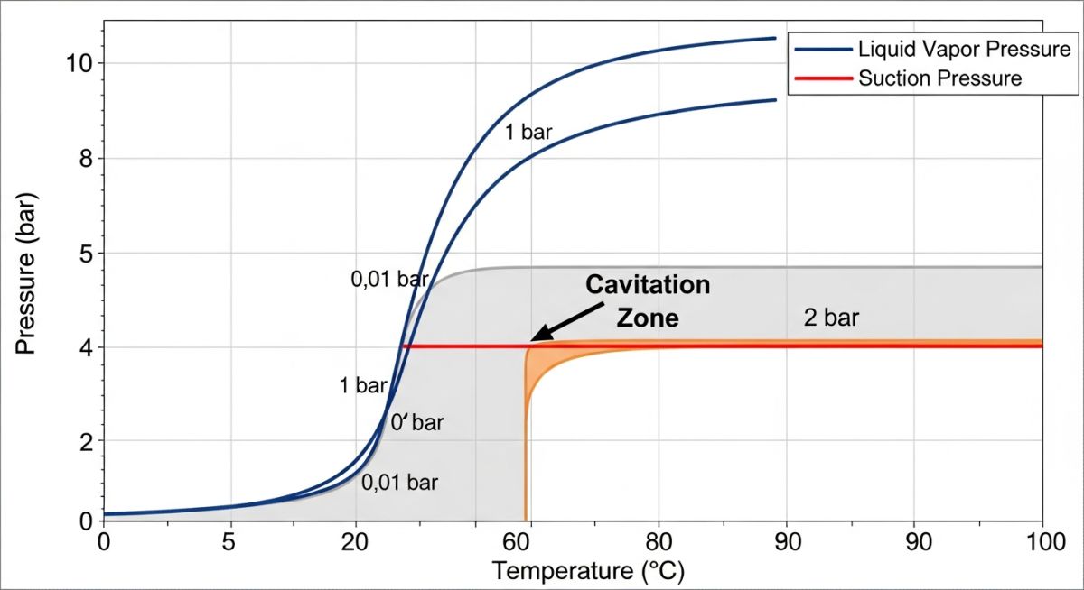
Temperature Fluctuations: Vapor pressure is highly sensitive to temperature. A 10°F increase in process fluid temperature can double the vapor pressure, instantly turning a "safe" system into a zone for active Centrifugal Pump Cavitation. Always design for the "worst-case" summer ambient temperature.
-
Forensic Distinction: If you see damage on the *pressure* side of the vane or near the discharge, you likely aren't dealing with classical cavitation. That is often "Discharge Recirculation," which occurs at low flow rates and mimics the sound of Centrifugal Pump Cavitation but requires a completely different hydraulic fix.
