Cryogenic Air Separation Process: Engineering Guide to ASU Design (2026)
You are managing a multi-ton-per-day steel production facility, and the Oxygen purity suddenly drops below 99.5%, threatening the entire melt cycle. In the high-stakes world of industrial gas production, the Cryogenic Air Separation Process is the only method capable of delivering the massive volumes and ultra-high purities required for modern heavy industry. This guide strips away the fluff to provide a deep-dive into the thermodynamics, column dynamics, and 2026 efficiency benchmarks of Air Separation Units (ASU).
Key Engineering Takeaways
- ✔ The Cryogenic Air Separation Process remains the superior choice for high-volume production, achieving 99.9% purity for Oxygen and Nitrogen.
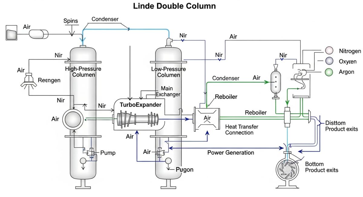
- ✔ Understanding the Linde Double Column system is critical for optimizing heat integration between the condenser and reboiler.
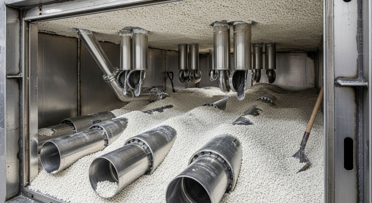
- ✔ 2026 standards focus on Turboexpander efficiency and Molecular Sieve pre-purification to reduce specific power consumption.
What is the Cryogenic Air Separation Process?
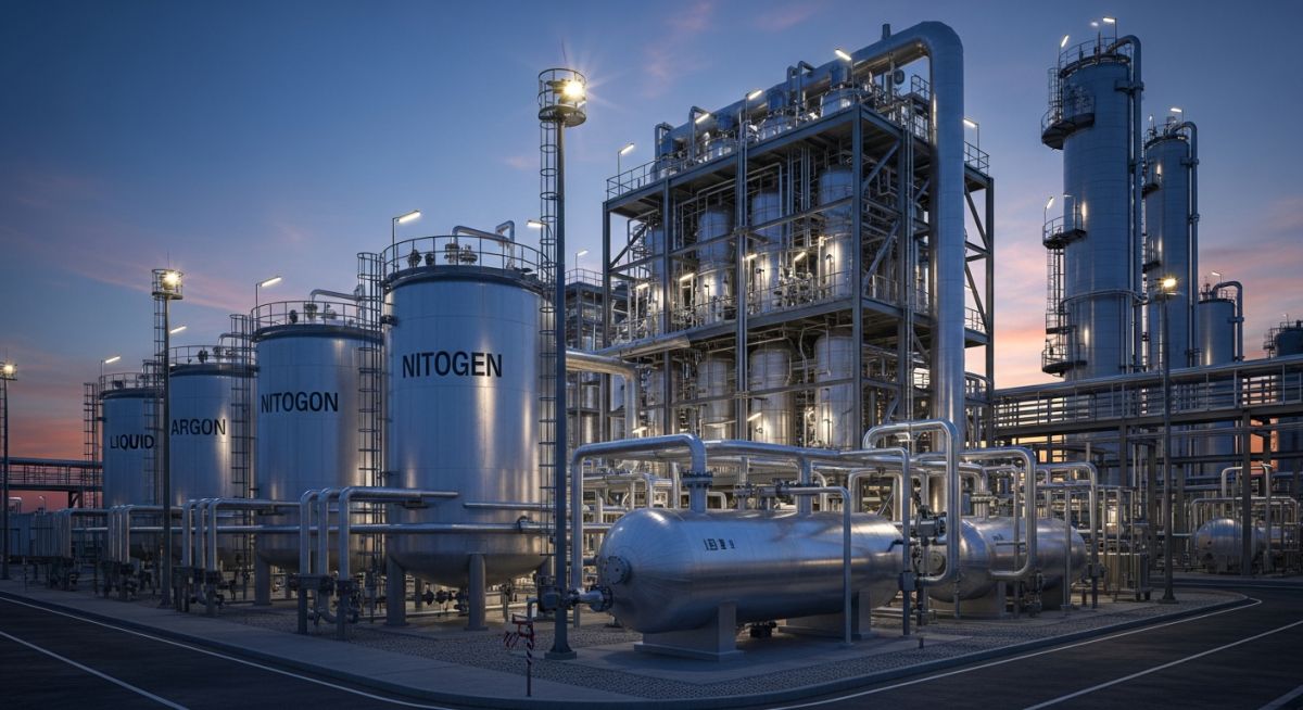
The Cryogenic Air Separation Process is an industrial method that liquefies atmospheric air and separates it into high-purity Oxygen, Nitrogen, and Argon through fractional distillation at extremely low temperatures (below -150°C). It utilizes the Linde Double Column arrangement to achieve high recovery rates through precise pressure and temperature control.
Founder’s Insight
“In my 20 years of commissioning ASUs, the most common failure point isn’t the distillation column itself, but the pre-purification unit. If your Molecular Sieve fails to catch trace CO2 or moisture, it will freeze solid in the Main Heat Exchanger, leading to a costly shutdown. Always prioritize the front-end cleanup to protect your Cryogenic Air Separation Process integrity.”
— Atul Singla, Founder of EPCLand
Table of Contents
Complete Course on
Piping Engineering
Check Now
Key Features
- 125+ Hours Content
- 500+ Recorded Lectures
- 20+ Years Exp.
- Lifetime Access
Coverage
- Codes & Standards
- Layouts & Design
- Material Eng.
- Stress Analysis
Technical Proficiency Check
Test your knowledge on the Cryogenic Air Separation Process
Which component is responsible for the final thermal separation of liquid air into pure Oxygen and Nitrogen?
Thermodynamic Basics of the Cryogenic Air Separation Process
The Cryogenic Air Separation Process is governed by the principles of fractional distillation and the Joule-Thomson effect. Unlike ambient temperature separations, this process requires the air to be cooled until it reaches a liquid state—typically below -180°C. The fundamental challenge in engineering an Air Separation Unit (ASU) is the management of the refrigeration cycle. High-pressure air is expanded through a turboexpander, creating the necessary cooling to overcome heat ingress from the surroundings and the heat of compression.
Inside the distillation column, separation occurs based on the differing boiling points of atmospheric gases at specific pressures. At standard atmospheric pressure, Nitrogen boils at -195.8°C, while Oxygen boils at -183°C. This 12.8°C difference is the thermodynamic “window” that the Cryogenic Air Separation Process exploits. By using a Linde Double Column, engineers can integrate the condenser of the high-pressure column with the reboiler of the low-pressure column, significantly enhancing energy efficiency and product purity.
According to the American Society of Mechanical Engineers (ASME), the pressure vessel integrity within the Cold Box is paramount due to the extreme thermal stresses caused by these cryogenic gradients. Modern plants in 2026 utilize advanced plate-fin heat exchangers (BAHX) to achieve a “warm end” temperature approach of less than 2°C, ensuring that the maximum amount of refrigeration is recovered within the system.
Dominant Cryogenic Air Separation Process Technologies
While several methods exist for industrial gas production, the Cryogenic Air Separation Process is the gold standard for high-purity applications. It competes primarily with Pressure Swing Adsorption (PSA) and Membrane Separation, but maintains a dominant market share for large-scale liquid gas production.
Membrane Separation
Uses hollow-fiber membranes to separate gases based on diffusivity. Ideal for low-purity Nitrogen (95-99%) in remote or portable applications.
Pressure Swing Adsorption
Utilizes Zeolite or Carbon Molecular Sieves to adsorb N2 or O2 under pressure. Efficient for small to medium scale gaseous O2/N2.
Cryogenic Distillation
The only process capable of 99.999% purity and large-scale liquid production via the Cryogenic Air Separation Process.
Cryogenic Air Separation Process vs. PSA and Membrane Separation
When selecting an industrial gas solution, the Cryogenic Air Separation Process is evaluated against non-cryogenic alternatives. While Pressure Swing Adsorption (PSA) offers lower CAPEX for small-scale gaseous needs, it cannot compete with the economies of scale or the multi-product flexibility (O2, N2, and Ar) provided by a cryogenic ASU.
| Feature | Cryogenic Distillation | PSA / VPSA | Membrane |
|---|---|---|---|
| Oxygen Purity | Up to 99.9% | 90% – 95% | 40% – 50% |
| Capacity Scale | Large (>5000 TPD) | Small to Medium | Very Small |
| Phase of Product | Liquid & Gaseous | Gaseous Only | Gaseous Only |
| Argon Recovery | Possible | Impossible | Impossible |
Energy Consumption Analysis of the Cryogenic Air Separation Process
Energy efficiency is the primary driver of 2026 ASU design. The Cryogenic Air Separation Process is an energy-intensive operation, with the Main Air Compressor (MAC) accounting for approximately 70-80% of the total plant power. To optimize this, engineers adhere to ISO 50001 Energy Management Standards, focusing on isothermal compression efficiency.
Advanced Cryogenic Air Separation Process plants now integrate “Pumped LOX” cycles. Instead of compressing gaseous oxygen at the outlet (which is hazardous and energy-expensive), liquid oxygen is pumped to high pressure and then vaporized in the main heat exchanger against high-pressure incoming air. This internal compression cycle significantly reduces the specific power consumption per ton of oxygen produced.
Furthermore, the integration of API 617 compliant centrifugal compressors ensures that the air is delivered at the precise pressure required to overcome the pressure drop in the Molecular Sieve beds and the distillation trays. Any deviation in compressor performance directly impacts the refrigeration balance of the Cryogenic Air Separation Process, leading to reduced liquid yields.
ASU Specific Power Estimator (2026)
Estimate the power requirements for your Cryogenic Air Separation Process based on production capacity.
Based on a 2026 standard specific energy consumption for a typical Cryogenic Air Separation Process.
EPCLand YouTube Channel
2,500+ Videos • Daily Updates
Engineering Case Study: 2000 TPD ASU Optimization
The Challenge: Liquid Yield Loss
A major metallurgy complex reported a 15% drop in liquid oxygen recovery within their Cryogenic Air Separation Process train. Initial diagnostic data suggested an increase in the “warm-end” temperature approach, indicating heat exchanger fouling or perlite settling within the Cold Box.
Upon detailed inspection, engineers discovered that the vacuum-jacketed piping had developed a microscopic leak, degrading the insulation vacuum and causing massive heat ingress into the low-pressure column.
The Technical Solution
- 1. Perlite Top-up: Re-pressurized the cold box and added 5 tons of expanded perlite to eliminate voids.
- 2. Expander Tuning: Re-calibrated the Turboexpander nozzles to increase refrigeration output by 8% to compensate for the delta-T loss.
- 3. Result: Restored LOX purity to 99.7% and reduced specific power consumption by 0.04 kWh/Nm3.
Don’t miss this video related to Cryogenic
Summary: On March 20, 1989, a catastrophic foundation failure caused 7000 tons of liquid ammonia to explode from its containment….
Expert Insights: Lessons from 20 years in the field
Refining the Cryogenic Air Separation Process requires more than just following a P&ID; it demands an intuitive understanding of how trace contaminants and mechanical tolerances interact at sub-zero temperatures. Based on two decades of ASU commissioning and troubleshooting, here are the critical technical levers:
-
01.Manage the Argon Side-Draw: If you are recovering Argon, the placement of the “Argon Wing” draw is hypersensitive. A shift of just two trays in your Cryogenic Air Separation Process model can lead to Nitrogen breakthrough, poisoning your Argon catalyst and halting production.
-
02.Avoid ‘Dead Pockets’ in Piping: At cryogenic temperatures, any stagnant liquid oxygen (LOX) in a pocket can accumulate hydrocarbons. Always ensure your piping slopes back toward the reboiler or a dedicated LOX filter to maintain Cryogenic Air Separation Process safety.
-
03.Turboexpander Wheel Clearance: Efficiency is won or lost in the micron-level clearances of the turboexpander. Even minor thermal cycling can cause rubbing or efficiency loss. In 2026, we prioritize active magnetic bearings to maintain peak Cryogenic Air Separation Process refrigeration.
-
04.Molecular Sieve Breakthrough: Never trust your CO2 analyzer alone. Correlate it with the pressure drop (DP) across the main heat exchanger. A rising DP is a lagging indicator of a failing PPU, even if the analyzer shows “clean” air.
Frequently Asked Questions: Cryogenic Air Separation Process
Why is the Cryogenic Air Separation Process preferred over PSA for large scales? ▼
What is the energy consumption of a typical ASU in 2026? ▼
What is the role of the Linde Double Column? ▼
How do you handle Hydrocarbon buildup in a liquid oxygen reboiler? ▼
What happens if the Molecular Sieve fails to remove moisture? ▼
Can an ASU be located in highly polluted industrial zones? ▼
📚 Recommended Resources: Cryogenic Air Separation Process
Read these Guides

Related posts:
![Industrial worker welding a large structural steel I-beam in a fabrication facility.]()
What is Structural Steel Fabrication and How Does It Work?
![A heavy-duty stainless steel turnbuckle tensioning a structural cable.]()
What is a Turnbuckle and How to Install It?
![Stack of newly manufactured galvanized steel pipes in an industrial warehouse]()
Understanding the Galvanized Pipe Meaning in Modern Piping Systems
![Industrial Alloy 625 piping components in a manufacturing plant]()
What is Alloy 625? Properties, Grades, and Applications of Alloy 625
![Close-up of a fractured steel shaft showing metal fatigue beach marks and failure zones.]()
What is Metal Fatigue and How Do Engineers Prevent It?
![Industrial machinery fitted with smart sensors displaying real-time condition-based maintenance data on a digital overlay.]()
What is Condition-Based Maintenance and How Does It Work?