Pressure Safety Valve Sizing and Relief Calculation Standards
Pressure Safety Valve Sizing is the critical engineering process of determining the required orifice area of a relief device to protect pressurized equipment from overpressure scenarios. In 2026, adhering to API 520 and ASME Section VIII standards is mandatory for ensuring plant safety and regulatory compliance during process upsets.
What is Pressure Safety Valve Sizing?
Pressure Safety Valve Sizing involves calculating the minimum effective orifice area (A) required to discharge a specific mass flow rate (W) or volumetric flow rate (Q) at a defined overpressure. This calculation utilizes factors like the discharge coefficient (Kd), backpressure correction (Kw), and fluid properties to ensure the valve prevents vessel rupture.
Engineering Knowledge Check
Question 1 of 5Which API standard provides the primary guidelines for the sizing and selection of relief valves in refineries?
Complete Course on
Piping Engineering
Check Now
Key Features
- 125+ Hours Content
- 500+ Recorded Lectures
- 20+ Years Exp.
- Lifetime Access
Coverage
- Codes & Standards
- Layouts & Design
- Material Eng.
- Stress Analysis
Fundamental Pressure Safety Valve Sizing Terms and Definitions
To master Pressure Safety Valve Sizing, engineers must first align with the standardized vocabulary established by ASME and API. These terms define the operational limits and mechanical response of the relief system during a process excursion.
Set Pressure
The inlet gauge pressure at which the relief valve is adjusted to open under service conditions. This is the starting point for all Pressure Safety Valve Sizing activities.
Overpressure
The pressure increase over the set pressure of the relieving device, usually expressed as a percentage. For non-fire scenarios, this is typically 10%.
Accumulation
The pressure increase over the Maximum Allowable Working Pressure (MAWP) of the vessel during discharge through the relief valve.
Blowdown
The difference between the set pressure and the re-seating pressure of the valve, ensuring the system stabilizes after a relief event.
API 520 Criteria for Relief Device Sizing
The Discharge Coefficient (Kd) is perhaps the most vital LSI term in the API 520 methodology. It represents the ratio of the actual flow rate to the theoretical flow rate. For most certified valves in 2026, the effective coefficient of discharge (Kd) for vapors is 0.975, while for liquids, it typically ranges between 0.62 and 0.65 depending on the trim design.
Pressure Safety Valve Sizing for Liquid Service
When performing Pressure Safety Valve Sizing for liquids, the calculation must account for the fluid’s viscosity and the potential for backpressure in the discharge header. Unlike compressible gases, liquids require a specific approach to address the Reynolds Number (Re) if the fluid is highly viscous.
Calculating the Effective Orifice Area for Liquids
Per API 520 Part I, the required Effective Orifice Area for a liquid relief valve is calculated using the following variables: Q (Flow rate), G (Specific Gravity), and P1 – P2 (Differential Pressure).
Note: In 2026, the Overpressure Allowance for liquid service is often set at 10% for ASME Section VIII compliance, but 25% may be used in specific thermal expansion cases where the PSV is not the primary protection for a vessel.
| Parameter | Symbol | Description |
|---|---|---|
| Required Capacity | Q | The volumetric flow rate at relieving conditions (US Gallons per minute). |
| Effective Coefficient | Kd | The certified discharge coefficient for the specific valve model. |
| Backpressure Factor | Kw | Correction for balanced bellows valves subject to backpressure. |
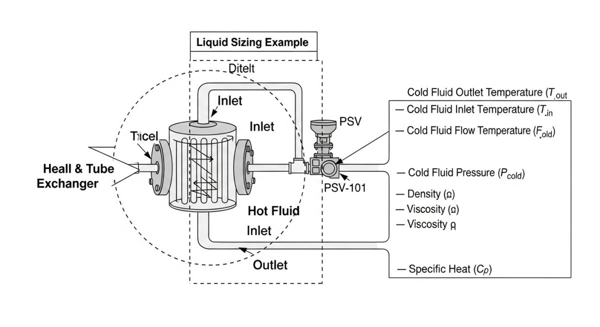
Case Study: Liquid Pressure Safety Valve Sizing Example
Practical Pressure Safety Valve Sizing requires applying API formulas to real-world scenarios. In this example, we calculate the required orifice area for a thermal expansion relief scenario on the cold side of a shell-and-tube heat exchanger.
Input Data:
- Fluid: Water (Specific Gravity G = 1.0)
- Required Flow (Q): 50 USGPM
- Set Pressure: 150 psig
- Backpressure: 15 psig (Constant)
- Overpressure Allowance: 10 percent
Relieving Pressure Calculation:
P1 (Relieving Pressure) = Set Pressure + Overpressure + Atmospheric Pressure
P1 = 150 + 15 + 14.7 = 179.7 psia
The differential pressure (delta P) for Pressure Safety Valve Sizing is the difference between the set pressure (plus overpressure) and the backpressure.
Pressure Safety Valve Sizing for Gas and Vapor Service
When performing Pressure Safety Valve Sizing for gases, engineers must determine if the flow is in a Critical vs Sub-critical Flow Regime. This is governed by the pressure ratio between the inlet and the outlet of the nozzle.
Critical vs Sub-critical Flow Regimes
Critical flow occurs when the velocity at the throat of the orifice reaches the speed of sound. This happens when the ratio of the downstream pressure (P2) to the upstream relieving pressure (P1) is less than or equal to the critical pressure ratio (rc).
| Flow Condition | Pressure Ratio Criteria | Sizing Formula Type |
|---|---|---|
| Critical Flow | P2 / P1 ≤ [2 / (k+1)] k/(k-1) | Standard API 520 Critical Flow Equation |
| Sub-critical Flow | P2 / P1 > [2 / (k+1)] k/(k-1) | Low Pressure / Flashing Flow Correction |
Step-by-Step Gas Relief Sizing Example
For 2026 industrial compliance, the Effective Orifice Area (A) for gas service is calculated using the mass flow rate (W), compressibility factor (Z), and the Relieving Pressure Calculation.
Gas Sizing Equation (USC Units):
A = W / (C * Kd * P1 * Kb * Kc) * √(T * Z / M)
Industry References and ASME Code Compliance
Regulatory bodies mandate strict adherence to specific codes when performing Pressure Safety Valve Sizing. The primary references used globally include:
Pressure Safety Valve Sizing Calculator (Liquid)
Note: This calculator uses the simplified API 520 liquid sizing formula for preliminary Pressure Safety Valve Sizing. It assumes a viscosity correction factor (Kv) of 1.0.
Don’t miss this video related to Pressure Safety Valve Sizing
Summary: Master Piping Engineering with our complete 125+ hour Certification Course: ……
Industrial Case Study: Pressure Safety Valve Sizing for Thermal Expansion
1. Project Data
A petrochemical facility in 2026 required Pressure Safety Valve Sizing for a crude oil preheater. The cold side (tube side) was susceptible to overpressure if blocked-in while the hot shell-side fluid continued to flow, causing thermal expansion of the trapped liquid.
- Design Pressure: 350 psig
- Operating Temp: 180°F
- Relieving Fluid: Crude Oil (SG 0.85)
2. Failure Analysis
Initial audit found that the existing relief valve was sized based on a generic 10 USGPM rule of thumb. However, a rigorous Relieving Pressure Calculation revealed that during a pump-deadhead combined with thermal expansion, the required flow rate was actually 24.5 USGPM to stay within the 10% overpressure limit.
3. Engineering Fix & Results
Corrective Action
Upgraded from a “D” orifice to an “E” orifice (0.196 sq in) to accommodate the higher volumetric expansion rate.
Compliance Result
Validated that the Effective Orifice Area provided sufficient capacity to limit peak pressure to 385 psig (110% of MAWP).
Lessons Learned
Never rely on “rule of thumb” values for Pressure Safety Valve Sizing. Always use the API 520 Part I thermal expansion formula: Q = (BH) / (500GCp), where B is the cubical expansion coefficient and H is the total heat transfer rate.
Common Questions on Relief Valve Engineering
How does the Discharge Coefficient (Kd) affect the final Pressure Safety Valve Sizing? ▼
When should a Backpressure Correction Factor (Kw) be applied? ▼
What is the difference between Critical and Sub-critical flow in relief sizing? ▼
Is an Overpressure Allowance of 21% always permitted for fire cases? ▼
Final Engineering Summary
Effective Pressure Safety Valve Sizing is the cornerstone of industrial overpressure protection. By 2026 standards, utilizing the latest API 520 methodologies ensures that your Relieving Pressure Calculation and orifice selection provide maximum safety for personnel and equipment. Whether you are dealing with liquid thermal expansion or critical gas flow, accurate Pressure Safety Valve Sizing remains the most vital task in process safety management.
Always verify calculated results with the manufacturer’s certified “K” values before final procurement.
📚 Recommended Resources: Pressure Safety Valve Sizing
Read these Guides
- 📄 Reciprocating Compressor Sizing Guide: API 618 Engineering Standards (2026)
- 📄 Valves in Piping: Types, Selection, Standards & Components (2026)
- 📄 Bypass Valve Engineering: Purpose, Working, and Selection Guide 2026
- 📄 Understanding Rupture Disk Devices: Safety and Standards in Pressure Relief Systems