Carbon Equivalent Formula: Complete Engineering Guide
The Carbon Equivalent Formula is the critical metallurgical calculation used by welding engineers to predict the hardenability of steel and assess the risk of cold cracking during fabrication. By standardizing the impact of various alloying elements into a single numerical value, this method allows engineers to determine the specific weldability of steel and establish necessary preheat protocols to ensure structural integrity.
What is Carbon Equivalent (CE)?
Carbon Equivalent (CE) is an empirical value derived from the chemical composition of steel. It equates the hardening effects of alloying elements (like Manganese, Chromium, and Molybdenum) to that of Carbon. A higher CE value indicates higher hardenability and a greater risk of hydrogen induced cracking in the Heat Affected Zone (HAZ).
⚡ Quick Navigation
Engineering Knowledge Check
1 / 5Loading Question…
✓ Explanation:
✗ Incorrect:
Complete Course on
Piping Engineering
Check Now
Key Features
- 125+ Hours Content
- 500+ Recorded Lectures
- 20+ Years Exp.
- Lifetime Access
Coverage
- Codes & Standards
- Layouts & Design
- Material Eng.
- Stress Analysis
The Science Behind the Carbon Equivalent Formula
In metallurgy, the Carbon Equivalent Formula serves as the bridge between raw chemical composition and practical fabrication guidelines. Steel is rarely just iron and carbon; it contains manganese, chromium, molybdenum, vanadium, and silicon. While these alloying elements improve strength and corrosion resistance, they also inadvertently increase the “hardenability” of the steel.
When steel is welded, the area immediately adjacent to the weld pool—known as the Heat Affected Zone (HAZ)—undergoes a rapid heating and cooling cycle. If the steel has high hardenability (indicated by a high CE value), this rapid cooling encourages the formation of martensite, a hard, brittle microstructure.
Martensite, combined with the presence of hydrogen (from moisture in the electrode or atmosphere) and residual stress, creates the “perfect storm” for Hydrogen Induced Cracking (HIC). Therefore, the primary goal when you calculate CE value is to assess how “carbon-like” the alloy mixture is, predicting its tendency to crack.
Standard Formulas: IIW vs. Pcm
There isn’t a single universal equation. The industry relies on two primary standards depending on the carbon content of the material.
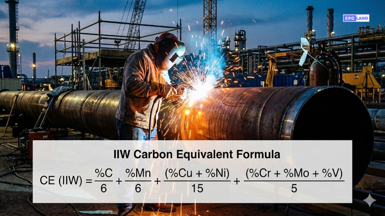
1. The IIW Carbon Equivalent Equation
Adopted by the International Institute of Welding (IIW) and AWS D1.1. This is the standard for structural steels with Carbon content > 0.18%.
CEIIW = C + (Mn/6) + (Cr+Mo+V)/5 + (Ni+Cu)/15
- C = Carbon percentage
- Mn = Manganese (major hardener)
- Cr, Mo, V = Carbide formers (strong effect)
- Ni, Cu = Austenite stabilizers (weaker effect)
2. The Pcm Critical Metal Parameter
Developed for modern Low Carbon Low Alloy (LCLA) steels, typically used in pipelines (API 5L) where Carbon content is < 0.16%. The IIW formula often overestimates hardness in these clean steels.
Pcm = C + (Si/30) + (Mn+Cu+Cr)/20 + (Ni/60) + (Mo/15) + (V/10) + 5B
Note the inclusion of Boron (B) and Silicon (Si) in this formula.
How to Calculate CE Value Step-by-Step
To perform an accurate assessment, you need the Mill Test Report (MTR) for the specific heat of steel you are using. Do not rely on generic material grade specifications (e.g., “ASTM A36 nominal”), as the actual chemistry varies by batch.
// EXAMPLE: ASTM A572 Grade 50 Plate
// Step 1: Identify Formula
Carbon is < 0.18%, but standard structural code usually prefers IIW. We will use IIW.
// Step 2: Plug in Values
CE = 0.16 + (1.25/6) + (0.10 + 0.05 + 0.04)/5 + (0.20 + 0.25)/15
CE = 0.16 + 0.208 + (0.19)/5 + (0.45)/15
CE = 0.16 + 0.208 + 0.038 + 0.030
// Step 3: Final Result
CE = 0.436%
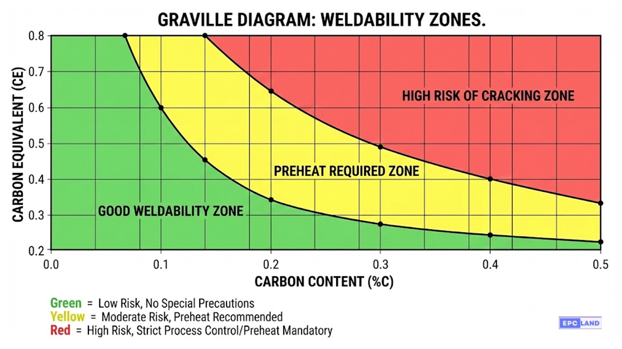
The result is 0.436%. This places the steel in the “Preheat Required” zone. Without calculation, one might assume standard welding procedures apply, risking a catastrophic failure.
Interpreting Results: Weldability of Steel
Once the Carbon Equivalent Formula yields a result, engineers must categorize the steel to determine the preheat temperature requirements. Preheating slows down the cooling rate, allowing hydrogen to diffuse out of the weld and preventing the formation of brittle phases.
| CE Value (IIW) | Weldability Status | Risk Level | Typical Action |
|---|---|---|---|
| Up to 0.35% | Excellent | Low | No preheat required (unless ambient temp < 0°C). |
| 0.36% – 0.40% | Good | Moderate | Preheat optional; recommended for thick sections (>25mm). |
| 0.41% – 0.50% | Fair | High | Preheat Mandatory (100°C – 150°C). Low Hydrogen Electrodes required. |
| > 0.50% | Poor | Critical | Strict Preheat (200°C+), Interpass control, and Post Weld Heat Treatment (PWHT). |
*Note: Always consult specific codes (ASME B31.3, AWS D1.1, or API 1104) as thickness and constraint also dictate final temperatures.
Case Study: API 5L X65 Pipeline Failure
Investigating Heat Affected Zone (HAZ) cracking due to Carbon Equivalent miscalculation.
Project Parameters
- Asset: 24-inch Gas Transmission Line
- Material: API 5L X65 (High Strength Low Alloy)
- Thickness: 25.4mm (1 inch)
- Ambient Temp: 5°C (Winter Conditions)
Welding Parameters
- Process: SMAW (Shielded Metal Arc Welding)
- Electrode: E8010-P1 (Cellulosic)
- Preheat Applied: None (Ambient)
- Outcome: Hydrotest Failure @ 85% SMYS
1. The Failure Scenario
During the construction of a natural gas spur line, the welding contractor utilized a standard Welding Procedure Specification (WPS) that had been successfully used for Grade X52 pipe. The assumption was that the jump to Grade X65 was minor. No specific preheat was applied because the ambient temperature was above freezing (5°C).
During the hydrostatic pressure test, a leak was detected at a circumferential field weld. Nondestructive Testing (NDT) via Ultrasonic Testing (UT) confirmed transverse cracks originating in the HAZ.
2. Root Cause Analysis (RCA)
The forensic metallurgical analysis required a review of the Mill Test Reports (MTR). The engineers had assumed a “Nominal” chemistry based on generic API 5L specs, but the actual heat of steel delivered was richer in Manganese and Vanadium to achieve the X65 strength requirements.
The Calculation Gap:
CE (IIW) = 0.42%
Risk: Moderate (Preheat often skipped).
CE (IIW) = 0.53%
Risk: CRITICAL (High Hardenability).
The actual CE value of 0.53% pushed the steel deep into the “Poor Weldability” zone. The combination of high CE, thick wall section (25.4mm), low ambient temperature, and high-hydrogen cellulosic electrodes (E8010) guaranteed hydrogen induced cracking.
3. The Engineering Solution
To rectify the situation and salvage the remaining pipe segments, the welding engineering team implemented a revised protocol based on the correct Carbon Equivalent Formula data:
- Mandatory Preheat: Established a minimum preheat temperature of 150°C (300°F) to slow the cooling rate.
- Consumable Change: Switched from Cellulosic (high hydrogen) to Low Hydrogen electrodes (E8018-C3) for the fill and cap passes.
- Interpass Control: Maintained specific interpass temperatures to prevent martensite formation between passes.
Result
0% repair rate on subsequent welds. The project passed 100% X-Ray and Hydrotest requirements.
Advanced Considerations: Beyond the Basics
1. The AWS Formula & The “Silicon Factor”
While the IIW formula is the global standard for pipelines, certain structural applications and older revisions of the American Welding Society (AWS) standards utilize a variation that explicitly accounts for Silicon (Si).
CEAWS = C + (Mn + Si)/6 + (Cr + Mo + V)/5 + (Ni + Cu)/15
Why include Silicon?
Silicon acts as a deoxidizer but also contributes to solid solution hardening. In steels where Si content is significant (>0.50%), the standard IIW formula might slightly under-predict the hardening risk. This formula provides a more comprehensive check for general structural components.
Comparison Note
IIW (Standard): Conservative for Pipelines & Pressure Vessels.
AWS (w/ Si): Broad application for structural shapes where Si variation is common.
2. Types of Cracking: Hot vs. Cold
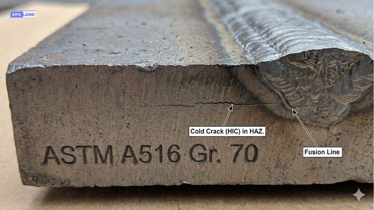
The Carbon Equivalent (CE) primarily predicts Cold Cracking, but a holistic welding engineering approach must consider all failure modes.
Cold Cracking (HIC)
Hydrogen Induced Cracking
- Cause: High CE + Hydrogen + Stress.
- Timing: Occurs after cooling (<400°F) or up to 48 hours later.
- Location: HAZ (Heat Affected Zone).
- Fix: Preheat & Low-H Electrodes.
Hot Cracking
Solidification Cracking
- Cause: Impurities (Sulfur/Phosphorus) segregating at grain boundaries.
- Timing: Occurs during solidification (High Temp).
- Location: Center of the weld bead.
- Fix: Control Mn/S ratio & bead shape.
HAZ Cracking
Microstructural Failures
- Cause: Excessive grain growth or martensite formation.
- Timing: During cooling cycle.
- Location: Adjacent to fusion line.
- Fix: Control heat input & PWHT.
3. Variable Impact on Preheat Decisions
Calculating the CE is step one. Step two is adjusting for the physical realities of the fabrication site.
- Joint Geometry T-Joints and highly restrained Butt Joints act as significant “heat sinks” (thermal drainage). They cool 3x faster than simple plate overlays, often requiring a 20-30°C higher preheat than the standard table suggests.
-
Welding Process
SMAW (Stick): Often uses cellulosic electrodes (high hydrogen) = Requires Higher Preheat.
GMAW (MIG) / FCAW: Generally lower hydrogen potential & continuous heat input = May allow Lower Preheat. - Mitigation Beyond preheat, utilizing Post-Weld Heat Treatment (PWHT) acts as a “reset button” for the steel’s microstructure, tempering the martensite and relieving residual stress, which is critical for steels with CE > 0.60%.
EPCLand YouTube Channel
2,500+ Videos • Daily Updates
⚡ Live Carbon Equivalent Calculator
Enter your Material Test Report (MTR) values below to calculate IIW & Pcm instantly.
IIW Standard (Structural)
Pcm (Pipeline/Low Carbon)
Used if C < 0.16%
Frequently Asked Questions
When should I use the Pcm formula instead of the IIW equation?
You should use the Pcm critical metal parameter when dealing with modern Low Carbon Low Alloy (LCLA) steels, typically where the Carbon content is less than 0.16% (e.g., API 5L pipeline grades). The standard IIW equation tends to overestimate the hardenability of these cleaner steels, leading to unnecessarily high preheat prescriptions.
Is the Carbon Equivalent result the only factor for preheating?
No. While the weldability of steel is heavily dependent on CE, you must also consider material thickness (heat sink effect), joint restraint (residual stress), and the hydrogen content of your welding consumables. Even a steel with a low CE (0.35%) may require preheat if the plate is very thick (>50mm) or if the ambient temperature is below freezing.
Can I use the Carbon Equivalent Formula for Stainless Steel?
No. The IIW and Pcm formulas are specifically designed for Carbon and Carbon-Manganese steels. Stainless steels rely on different mechanisms for weldability assessment, typically involving the Schaeffler or WRC-1992 Diagrams to calculate Ferrite Number (FN) based on Chromium and Nickel Equivalents, rather than Carbon Equivalent.
What is the "Critical CE Value" for Hydrogen Induced Cracking?
General industry consensus suggests that a CE value above 0.40% significantly increases the risk of hydrogen induced cracking. However, for high-strength pipeline steels, this threshold might be lower (0.35% Pcm). Always consult the specific code (AWS D1.1 or ASME B31.3) governing your project.
