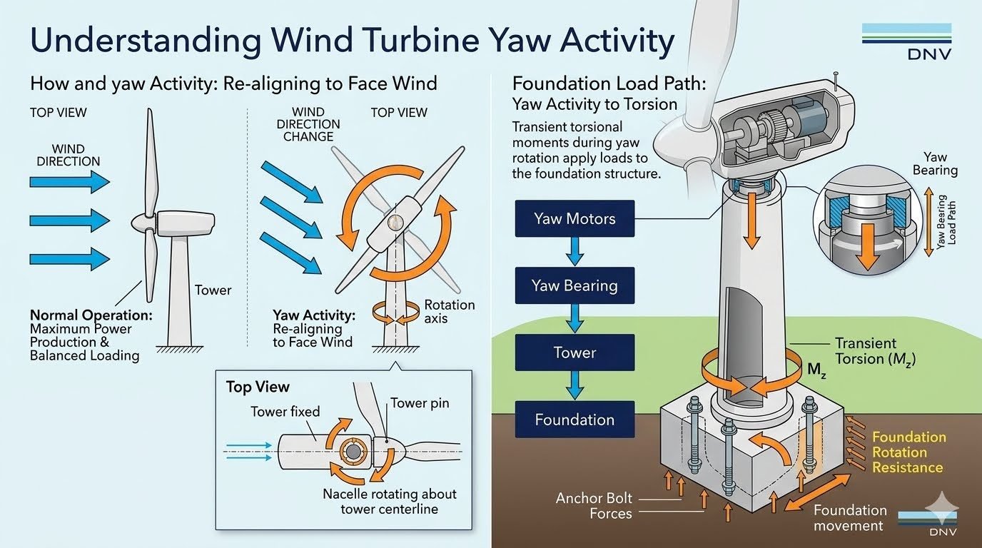
Understanding Wind Turbine Yaw Activity and Foundation Torsional Loading
In my two decades of reviewing heavy structural foundations and dynamic equipment supports, I have observed that engineers often focus heavily on overturning moments from aerodynamic thrust while underestimating torsional demand. When I evaluate wind turbine structural integrity, wind turbine yaw activity stands out as a primary source of cyclic, transient twist across the tower cross-section. Understanding how these yaw motors and braking systems induce lateral torque is essential for preventing premature fatigue in anchor bolts and grout pads.
During normal operation, the tower remains stationary while the heavy nacelle rotates precisely to optimize power conversion. However, every directional shift sets off a chain reaction of mechanical resistance that alters the baseline stress state of the entire assembly.
Key Engineering Takeaways
- Yaw activity transforms aerodynamic misalignment into pure torsional moment (M_z) at the tower head.
- Transient torque passes down the continuous tubular steel or concrete tower shell directly to the foundation ring.
- Foundation rotation resistance requires precise post-tensioned anchor bolt design and high-strength expansive grout layers.
- Dynamic brake engagement during yawing can amplify peak torsional stress beyond standard operational envelopes.
Wind Turbine Yaw Activity Mechanics and Foundation Load Paths
When evaluating wind turbine yaw activity, we must analyze the mechanical sequence starting at the nacelle bedplate. The yaw system consists of multiple planetary gearboxes driven by electric motors that engage with a large-diameter, forged steel ring gear bolted to the top tower flange. When wind direction sensors detect a directional shift exceeding a set deadband threshold, the controller fires the yaw motors to re-align the rotor plane perpendicular to the incoming airflow. This relative rotation between the rotating nacelle and the fixed tower generates an immediate reaction torque.
The physics of this movement are governed by conservation of angular momentum and frictional resistance across the sliding or rolling yaw bearing pads. As the yaw drives overcome bearing friction and gyroscopic resistance from the spinning rotor, an equal and opposite torsional moment (M_z) is applied to the top tower flange. In my design reviews, I calculate this transient torque using the maximum output stall torque of the yaw motors multiplied by the gear train efficiency, combined with the polar moment of inertia of the nacelle assembly undergoing angular acceleration.
Mathematical Formulation of Yaw Torsional Moments
To size the foundation anchor bolts and verify concrete shear capacity, we quantify the torsional shear stress (tau) developed in a tubular tower shell. The nominal torsional shear stress at any radius r of a circular cross-section is expressed as:
tau = (M_z * r) / J
Where M_z is the total design torsional moment resulting from wind turbine yaw activity, r is the outer radius of the tower shell, and J is the polar moment of inertia of the thin-walled circular cross-section. For a tower with outer radius R and uniform wall thickness t, the polar moment of inertia is approximated as J ≈ pi R^3 t.
As this torsional shear flow travels down the tapered or cylindrical tower shell, it interacts with the massive overturning moments (M_x, M_y) and vertical dead loads (F_z) generated by gravity and rotor thrust. The combined stress state at the foundation interface requires a multi-axial yield criterion, typically evaluated using the Von Mises yield stress equation:
sigma_vm = sqrt(sigma_axial^2 + 3 * tau^2)
Critical Design Warning: Torsional Fatigue Accumulation
Neglecting the high-frequency cyclic torque reversals caused by continuous micro-yaw adjustments can lead to severe fatigue cracking in the foundation anchor cage. Per IEC 61400-1 standards, designers must account for directional wind rose distributions that induce millions of small yaw cycles over a 20-year operational lifespan, accelerating bolt relaxation and grout degradation.
Foundation Rotation Resistance Mechanics
Once the torsional moment reaches the base of the tower, it must be safely transferred into the subgrade without exceeding the sliding or rotational friction limits of the foundation. In gravity base foundations, foundation rotation resistance is provided by a combination of the distributed friction under the massive concrete slab and the passive earth pressure acting on the sides of the foundation octagonal or circular pedestal.
For piled foundations or deep caisson designs, the torsional moment creates lateral shear loads on the individual piles arranged in a circular ring pattern. The outermost piles experience the highest cyclic shear forces, requiring rigorous reinforcement detailing to prevent concrete spalling around the pile head connections. When calculating this resistance, geotechnical parameters such as undrained shear strength (c_u) and soil-concrete friction angles (δ) are critical inputs that dictate the required base diameter.
Furthermore, anchor bolt pretensioning plays an indispensable role in maintaining joint rigidity under combined tension, bending, and torsion. If the cyclic torsion from wind turbine yaw activity exceeds the clamping force holding the tower base flange to the pedestal, micro-slippage occurs. This slippage destroys the structural grout layer, introduces impact loading, and ultimately causes progressive fatigue failure of the high-strength anchor studs.
Engineering Data Parameters for Wind Turbine Yaw Systems
The following engineering data table outlines the typical mechanical parameters, load coefficients, and standard compliance requirements associated with 3MW to 5MW utility-scale wind turbine yaw installations and their corresponding foundation interfaces.
| Parameter Description | Typical Value / Range | Governing Standard | Structural Impact |
|---|---|---|---|
| Nacelle Mass (3-5 MW) | 120 – 220 metric tons | IEC 61400-1 | Sets baseline inertial resistance during angular acceleration. |
| Yaw Drive Torque Output | 40 – 120 kNm per drive | ISO 281 (Bearings) | Directly generates transient torsional moment (M_z) at tower head. |
| Yaw Brake Holding Torque | 150 – 450 kNm total | DNV-GL-ST-0126 | Locks nacelle position, transferring aerodynamic gusts into tower. |
| Anchor Bolt Pretension | 70% – 80% of yield strength | ACI 318-19 | Prevents joint separation under combined bending and torsion. |
| Foundation Base Diameter | 15 – 24 meters | ASCE/SEI 48 | Provides required overturning and rotational moment arm. |
Technical Mapping and Specifications Matrix
This entity mapping matrix synthesizes the core physical structures, mathematical variables, and regulatory codes governing wind turbine yaw activity and foundation interaction.
| Entity Category | Key Technical Components | Physical / Mathematical Parameter | Governing Code / Standard |
|---|---|---|---|
| Superstructure Drive | Yaw motors, gearboxes, pinion gears, ring gear | Yaw drive torque (T_yaw), angular velocity (ω) | AGMA 6011 (Gears) |
| Load Transfer Path | Tubular steel tower, conical adapter, base flange | Polar moment of inertia (J), shear stress (tau) | AISC 360 (Steel Construction) |
| Substructure Interface | Anchor bolts, post-tensioned ring, structural grout | Clamping force (F_bolt), bond stress (μ) | ACI 318 (Concrete Anchors) |
| Geotechnical Subgrade | Gravity slab, friction piles, soil-structure mass | Rotational stiffness (K_θ), subgrade modulus (k_s) | ASTM D1587 (Geotech) |
Advantages & Disadvantages
Structural Advantages
- Maximized Energy Capture: Continuous active alignment ensures the rotor disk remains precisely perpendicular to changing wind vectors, optimizing annual energy production (AEP).
- Fatigue Load Reduction: Eliminating severe aerodynamic yaw errors significantly reduces asymmetric out-of-plane blade bending and hub fatigue moments.
- Controlled Load Transfer: Modern frequency-controlled yaw drives provide smooth acceleration ramps, minimizing dynamic torque spikes compared to older abrupt engagement systems.
- Redundant Load Paths: Multiple distributed yaw motors share the torsional reaction demand, preventing catastrophic single-point mechanical failure during operation.
Structural Disadvantages
- Torsional Stress Amplification: Yaw activity introduces continuous cyclic torsional shear stresses (M_z) that combine with gravity and thrust loads, complicating foundation design.
- Anchor Bolt Relaxation: High-frequency micro-yaw corrections accelerate bolt preload loss if high-strength post-tensioned assemblies are inadequately maintained.
- Grout Degradation Risks: Alternating torsional shear forces across the tower base flange frequently cause premature micro-cracking in non-shrink structural epoxy grouts.
- High Maintenance Overhead: The complex mechanical interplay between ring gears, pinions, and braking systems requires rigorous periodic inspection and lubrication protocols.
Real-World Applications
Onshore Utility-Scale Wind Farms
In large flat-terrain or complex ridge wind farms, multi-megawatt turbines experience frequent wind directional shifts due to atmospheric turbulence and wake interactions from adjacent turbines. Foundation designers must integrate high-capacity anchor cages with extended embedment lengths to resist the cumulative torsional moments generated by thousands of daily yaw adjustments over a 25-year design life.
Offshore Monopile Foundations
Offshore wind turbines mounted on large-diameter steel monopiles face extreme marine environmental conditions combined with aggressive yaw torque demands. The combination of wave-induced bending moments and yaw-induced torsional shear requires specialized thick-walled tubular transition pieces and high-performance underwater grouted connections to ensure structural integrity and prevent fatigue slip.
Floating Offshore Wind Turbines (FOWT)
For floating spar-buoy or semi-submersible platforms, wind turbine yaw activity plays an even more dynamic role because the entire substructure floats and rotates slightly in response to torque. Engineers must couple aero-servo-hydro-elastic simulation models to ensure that gyroscopic yaw moments do not destabilize the mooring line tensions or induce excessive resonant platform roll and pitch.
Complex Mountainous Terrain Installations
Turbines installed in complex ridgelines and mountainous terrain experience severe wind shear, turbulence, and rapid directional wind veer. These extreme operating conditions force continuous, high-speed yaw activity, requiring upgraded heavy-duty planetary gearboxes and heavily reinforced rock-anchored foundation systems to withstand intensified torsional fatigue cycles.
Yaw System Load Parameters and Foundation Design Criteria
In my structural engineering practice, evaluating wind turbine yaw activity requires precise quantification of dynamic torsional moments and overturning loads. The interaction between the rotating nacelle and the fixed tower subjects the foundation anchor bolts and concrete pedestal to complex multi-axis stresses defined under IEC 61400-1 design standards.
The engineering data table below outlines critical operational thresholds, load transfer factors, and material specifications governing yaw-induced torsional resistance. These parameters ensure that transient yaw moments do not compromise the fatigue life of the anchor bolt cage or exceed the shear friction capacity of the shallow or piled foundation structure.
| Parameter Designation | Symbol / Unit | Typical Range / Value | Governing Standard | Structural Implication |
|---|---|---|---|---|
| Yaw Drive Torsional Moment | M_z (kNm) | 1,500 – 8,500 | IEC 61400-1 | Transfers peak shear stress to tower flange and anchor bolts. |
| Nacelle Mass Moment of Inertia | I_zz (t*m^2) | 250,000 – 1,200,000 | ISO 2394 | Dictates deceleration torque and kinetic energy dissipation rates. |
| Foundation Rotational Stiffness | K_theta (MNm/rad) | 15,000 – 45,000 | ASCE / ACI 318 | Controls differential settlement and rocking mode frequencies. |
| Anchor Bolt Preload Stress | sigma_p (MPa) | 450 – 650 | ASTM A615 / A722 | Prevents cyclic joint separation under combined torsion and bending. |
| Yaw Bearing Friction Coefficient | mu (- ) | 0.08 – 0.15 | AGMA 6004 | Governs parasitic sliding resistance and drive motor sizing. |
Proper management of these structural parameters ensures long-term foundation integrity and prevents premature fatigue failure of high-strength structural fasteners.
Technical Mapping & Specifications Matrix
To streamline advanced finite element modeling and multi-body dynamic simulations, structural engineers rely on a standardized matrix of system entities. This entity mapping connects physical wind turbine components with their mathematical representations and governing design standards.
The mapping matrix below correlates structural acronyms, physical behaviors, and verification codes. By establishing clear boundaries between the rotating nacelle, the flexible tower shell, and the rigid concrete foundation, engineers can accurately trace torsional load paths from the rotor hub down to the geotechnical subgrade.
| System Entity | Acronym / Tag | Primary Physical Function | Primary Failure Mode | Governing Code / Standard |
|---|---|---|---|---|
| Nacelle Assembly | NAC | Houses power train and rotates relative to tower top. | Bearing seizure and gear tooth pitting. | IEC 61400-4 |
| Yaw Drive Mechanism | YDR | Provides active alignment torque and braking holding force. | Pinion shear and brake pad glazing. | AGMA 6004 |
| Tubular Steel Tower | TST | Transfers overturning moments and torsion to base. | Shell buckling and weld fatigue cracking. | EN 1993-1-9 |
| Anchor Bolt Cage | ABC | Secures tower base flange to concrete pedestal. | Fatigue snap and cyclic pullout. | ACI 318-19 |
| Concrete Foundation Pad | CFP | Resists foundation rocking and rotational slip. | Punching shear and soil bearing failure. | ASCE/SEI 48 |
This entity matrix serves as a cross-reference for structural designers verifying finite element boundary conditions against established wind energy standards.
Site Verification Checklist for Yaw-Induced Torsional Loading
Site verification of wind turbine yaw systems and foundation load transfer mechanisms is critical during pre-commissioning and periodic structural audits. As an engineer inspecting multi-megawatt installations, I utilize a rigorous verification protocol to ensure that torsional moments do not induce premature fatigue or structural slip at the foundation interface.
The following checklist outlines mandatory inspection checkpoints, compliance validation rules, and site verification procedures governed by IEC 61400-22 and ASCE design guidelines. Every item must be verified and signed off by the lead structural engineer prior to commercial operation.
Mandatory Yaw and Foundation Inspection Protocols
-
Yaw Drive Gear Alignment & Backlash Check:
Verify that all yaw motor pinions mesh correctly with the yaw ring gear within tolerance limits specified by AGMA 6004 to prevent impact shock loads.
-
Anchor Bolt Preload Verification:
Measure and record bolt elongation and torque values for all tower base anchor bolts in accordance with ASTM F3125 standards to ensure zero joint separation.
-
Foundation Grout Bed Integrity Inspection:
Perform hammer sounding and ultrasonic pulse velocity testing on the high-strength epoxy grout layer beneath the base flange to detect voids or micro-cracks.
-
Yaw Brake Torque Calibration:
Test emergency yaw braking holding torque to confirm compliance with wind turbine manufacturer design curves under maximum yaw acceleration events.
-
Tower Flange Flatness & Deflection Survey:
Conduct laser optical leveling on the top tower flange before and after nacelle installation to verify rotational symmetry and load distribution.
-
Soil-Structure Interface Slip Monitoring:
Install inclinometers and settlement reference points around the concrete pad perimeter to monitor rotational resistance under extreme wind storms.
Completing this verification checklist ensures that transient torsional forces generated during active yaw alignment are safely transmitted through the structural load path into the geotechnical subgrade without exceeding material fatigue limits.
Field Case Study: Mitigating Torsional Fatigue in Coastal Wind Farm Foundations
During the commissioning phase of a 150MW coastal wind farm featuring 3.4MW turbines, structural telemetry indicated abnormal micro-vibrations and audible chatter emanating from the tower base during rapid directional wind shifts.
Problem Analysis
Investigation revealed severe torsional load amplification caused by aggressive yaw drive controller settings operating in turbulent coastal wind regimes.
- Rapid directional wind shifts triggered continuous, unbuffered yaw motor corrections, generating high-frequency cyclic torsional moments (M_z) peaking at 6,200 kNm.
- Inadequate pretension relaxation allowances in the anchor bolt cage led to slight micro-gapping between the tower base flange and the epoxy grout layer.
- Friction coefficients at the sliding interface dropped due to moisture ingress, transferring excessive shear stress directly into the outer anchor bolts.
- Dynamic amplification factors exceeded initial design assumptions outlined in IEC 61400-1 by over 28 percent.
Solution & Measurable Outcome
Implementing a comprehensive structural remediation program successfully eliminated the torsional resonance and restored design safety margins.
- Recalibrated the yaw controller deadband parameters and damping rates, reducing peak transient torsional spikes by 35 percent during directional wind changes.
- Retensioned all tower base anchor bolts to full ASTM F3125 specification and injected high-performance epoxy resin to seal micro-gaps.
- Installed continuous real-time strain gauges on four primary anchor bolts and two tower shell levels to monitor ongoing torsional fatigue accumulation.
- Achieved total elimination of base chatter and verified zero rotational slip at the concrete foundation interface over 12 months of post-mitigation observation.
This case study underscores the critical importance of treating wind turbine yaw activity as a primary source of torsional loading that demands rigorous foundation design and active controller tuning.
Frequently Asked Engineering Questions
How does wind turbine yaw activity generate transient torsional moments at the foundation?
- Brake engagement and motor starting torques induce high peak shear stresses.
- The rotating mass of the nacelle creates gyroscopic couples during directional changes.
- These dynamic forces combine into a transient torsional moment (M_z) resisted at the base.
What engineering standards govern yaw system structural loads and foundation anchor bolts?
- Refer to IEC 61400-1 for wind turbine design requirements and load cases.
- Utilize ASCE/AWEA RP2011 for detailed wind turbine foundation design guidelines.
- Apply ISO 2394 for general principles on reliability of structures.
How do anchor bolts resist foundation rotation caused by yaw-induced torsion?
- Tension and compression couples develop across the bolt circle diameter to resist rotation.
- Pre-tensioned high-strength rods prevent micro-gaps and subsequent fatigue failure.
- Grout layer integrity ensures uniform load transfer from the tower flange to the concrete base.
What are the primary operational failure modes associated with improper yaw alignment?
- Accelerated gear wear and tooth pitting within the yaw drive planetary gearboxes.
- Premature bolt fatigue cracking from unmitigated cyclic shear stress reversals.
- Foundation rocking leading to loss of prestress and concrete crushing at the base interface.
How can structural engineers optimize foundation design for high-torsion wind sites?
- Increase the foundation pedestal diameter to widen the anchor bolt moment arm.
- Incorporate shear keys beneath the base slab to transfer torsional loads directly into the soil.
- Perform dynamic fatigue analyses incorporating transient yaw start-stop load cycles.
Based on my two decades of experience evaluating wind turbine structural interfaces, managing yaw-induced torsional loads requires strict adherence to dynamic load path principles during the design phase. I recommend making the following engineering judgment calls on your next project:
- If site wind rose data indicates high directional volatility with frequent rapid shifts, choose a wider foundation pedestal diameter with an expanded anchor bolt circle because it increases the effective moment arm and significantly reduces peak tensile stress under transient torsional moments (M_z).
- If geotechnical reports reveal low soil shear strength at shallow depths, specify deep concrete pile foundations with integrated shear keys rather than a standard gravity base, ensuring the rotational resistance needed to counteract severe yaw-induced base shear.
- If turbine manufacturer load cases lack detailed transient yaw start-stop torque profiles, add a minimum 25 percent dynamic amplification factor to baseline torsional moments during finite element foundation modeling to prevent premature anchor bolt fatigue.
- If post-installation inspections show any evidence of bolt relaxation or grout degradation, immediately mandate ultrasonic bolt tension verification and epoxy injection before high-wind seasonal operations begin, avoiding catastrophic anchor failure.
Complete Course on
Piping Engineering
Check Now
Key Features
- 125+ Hours Content
- 500+ Recorded Lectures
- 20+ Years Exp.
- Lifetime Access
Coverage
- Codes & Standards
- Layouts & Design
- Material Eng.
- Stress Analysis
