Mastering Wind Turbine Tower Flange Design and Foundation Connections
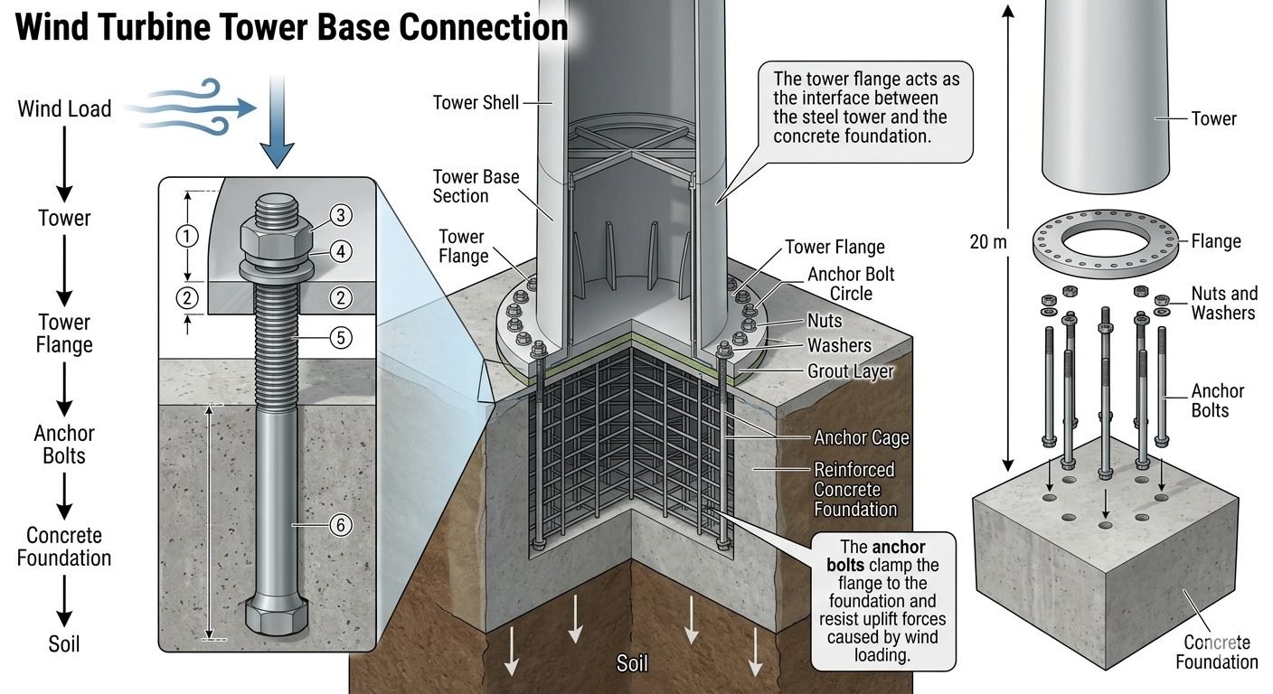
In my twenty-plus years of reviewing heavy industrial and renewable energy infrastructure, I have seen that the integrity of a utility-scale wind turbine depends entirely on how effectively dynamic wind loads are dissipated at the foundation interface. The load path does not forgive structural shortcuts. Extreme operational thrust forces generated by the rotor blades travel down the slender cylindrical tower shell, concentrating immense bending moments right at the base connection.
When designing or inspecting this critical joint, engineers must carefully evaluate how the tower flange distributes stress into the high-strength anchor bolt circle, the precision non-shrink cementitious grout layer, and the mass concrete pedestal below. A failure in pretensioning or flange flatness will quickly lead to fatigue cracking, bolt relaxation, and catastrophic structural distress.
Key Engineering Takeaways
- Comprehensive load transfer pathways dictate strict tolerances for flange perpendicularity and flatness.
- Anchor bolt pretensioning must overcome cyclic fatigue loads without exceeding yield thresholds.
- Grout layer compaction and void elimination are vital for uniform bearing pressure distribution.
Structural Mechanics of the Wind Turbine Tower Flange
Designing a utility-scale wind turbine base requires tracing the complete aerodynamic load path from the rotor swept area down to the subterranean geotechnical strata. Wind pressure creates intense horizontal thrust, which is converted into massive overturning moments at the base. These moments subject the leeward side of the connection to extreme compressive bearing pressures while simultaneously subjecting the windward anchor bolts to severe cyclic tension.
The tower flange itself acts as a rigid structural stiffener. Without a robust flange ring, the thin steel shell would buckle under localized point loads from the anchor bolts. Modern multi-megawatt turbines utilize massive forged steel rings, typically manufactured from quenched and tempered low-alloy steels such as 34CrNiMo6 or similar grades conforming to ISO 683-2 standards. These forged components must maintain high Charpy V-notch impact toughness values at sub-zero temperatures to prevent brittle fracture under dynamic gust loading.
Anchor Bolt Pretensioning and Cyclic Fatigue
Anchor bolts are the literal backbone of the wind turbine tower flange connection. Unlike static structural bolting, these high-strength threaded rods (frequently grade 10.9 or 12.9 carbon steel) experience tens of millions of stress reversals over a typical 25-year operational design life. To prevent fatigue failure, engineers must specify precise bolt pretensioning protocols using hydraulic tensioners rather than standard torque wrenches, eliminating frictional uncertainties.
The required initial preload must be calculated to ensure that the bolted joint never separates on the windward side during extreme gust events (often modeled using 50-year wind return periods per IEC 61400-1). If the preload is too low, the cyclic opening and closing of the joint leads to rapid bolt fatigue and snap-off. If the preload is excessive, combined tensile and bending stresses will exceed the ultimate tensile strength of the fastener during peak operational gusts.
Critical Engineering Warning: Bolt Relaxation
Initial bolt tension invariably experiences relaxation within the first three to six months of operation due to embedment loss, micro-cracking of the grout layer, and thermal creep. Post-installation torque checks and recalibration cycles are mandatory to maintain minimum residual clamping force across the tower flange interface.
The Foundation Grout Layer Interface
Sandwiched between the steel tower flange and the reinforced concrete foundation is a precision grout layer, typically 50 mm to 100 mm thick. This layer compensates for minor elevation discrepancies in the concrete pour and ensures uniform load transfer across the entire circular footprint. Using ordinary cement mortar is completely unacceptable; engineers must specify high-performance, non-shrink, fiber-reinforced epoxy or cementitious grouts with a minimum 28-day compressive strength exceeding 85 MPa.
Any void, honeycombing, or delamination within the grout layer creates a localized stress riser. Under continuous cyclic loading, these voids expand, leading to progressive crushing of the grout and subsequent tilting of the entire tower structure. Comprehensive ultrasonic pulse-velocity testing or hammer sounding is required during quality assurance inspections to verify complete void-free compaction beneath the entire circumference of the flange.
Advantages & Disadvantages of Tower Flange Connections
Engineering Advantages
- Modular Assembly: Flanged connections allow rapid site bolting of large tubular tower sections without requiring on-site welding.
- Predictable Load Transfer: Circular anchor bolt patterns provide symmetrical resistance against multi-directional wind shears.
- Adjustability: Leveling nuts beneath the flange allow precise vertical plumbness alignment of the turbine mast.
- Inspectability: External bolts and flange toes remain fully accessible for visual and non-destructive testing inspections.
- Fatigue Resistance: High-strength forged steel flanges absorb dynamic cyclic moments far better than unreinforced shell welds.
Engineering Disadvantages
- High Stress Concentration: Abrupt geometrical transitions create severe localized stress risers requiring thick forged sections.
- Maintenance Intensity: Anchor bolts demand routine torque and tension verification programs throughout the operational lifecycle.
- Grout Vulnerability: The underlying grout layer is highly sensitive to installation imperfections, moisture, and freeze-thaw cycles.
- Cost and Weight: Massive forged steel flanges and high-tensile fasteners add significant material and transportation costs.
Corrosion Susceptibility: Crevice corrosion between the flange mating surfaces can initiate if weatherproofing seals degrade.
Real-World Applications of Tower Flange Systems
Onshore Utility-Scale Wind Farms
In flat plains and rolling terrain, onshore turbines ranging from 3MW to 6MW utilize internal base flanges bolted to massive octagonal or circular gravity concrete foundations. These connections must withstand extreme atmospheric turbulence intensity while remaining economical to transport and assemble with standard crawler cranes.
Offshore Monopile Transitions
Offshore wind installations feature transition pieces where the submerged monopile meets the above-water tower section. The tower flange here operates in a highly corrosive marine atmosphere, requiring specialized duplex stainless steel or heavy protective coating systems alongside impressed current cathodic protection to prevent aggressive seawater degradation.
Complex Mountainous Terrain Wind Sites
Ridge-top wind developments subject turbine foundations to severe wind shear, asymmetric gust loading, and complex wake effects from adjacent peaks. The tower flange and anchor bolt cages must be engineered with higher safety factors and specialized rock-anchored foundation tie-downs to counteract extreme overturning moments.
Cold Climate and Arctic Installations
Sub-arctic wind projects expose tower flanges and anchor assemblies to extreme sub-zero temperatures where structural steel risks brittle fracture. Material selection mandates strict low-temperature impact testing, and foundation grout formulations must incorporate anti-freeze admixtures without sacrificing compressive strength.
Designing a robust wind turbine tower flange requires rigorous attention to material grades, bolt pre-tensioning targets, and geometrical tolerances. The data presented below outlines the operational thresholds and dimensional classifications typically observed in multi-megawatt onshore installations compliant with ASME and ISO frameworks.
Engineers must carefully cross-reference these operational values against local geotechnical reports and foundation stiffness matrices to prevent premature fatigue failure or bolt relaxation under cyclic wind loading.
| Parameter Classification | Standard Specification | Design Target / Tolerance | Governing Code |
|---|---|---|---|
| Tower Flange Steel Grade | S355NL / S460QL | Min 27J at -40°C Charpy V-notch | EN 10025-4 |
| Anchor Bolt Material | 42CrMo4 Quenched & Tempered | Property Class 10.9 (Yield > 900 MPa) | ISO 898-1 |
| Bolt Pre-tensioning Error | Hydraulic Tensioning Control | Maximum ±5% deviation from target preload | VDI 2230 |
| Grout Layer Compressive Strength | Non-Shrink Cementitious / Epoxy | Minimum 85 MPa at 28 days | ASTM C1107 |
| Flange Flatness Tolerance | Machined Contact Surface | Max 0.5 mm deviation across bolt circle | IEC 61400-1 |
Maintaining strict compliance with these metrics ensures that the dynamic overturning moments transferred from the turbine rotor are safely absorbed into the concrete foundation mass without causing localized crushing of the underlying grout bed.
The structural integrity of a wind turbine relies on a fully integrated matrix of mechanical components and material interfaces. In my professional practice, I utilize this entity mapping framework to cross-reference physical characteristics with their governing international standards during design reviews.
Reviewing these parameters allows structural teams to identify potential weak links in the load path before shop fabrication begins, minimizing costly on-site modifications or premature fatigue failures.
| Entity / Component | Primary Function | Critical Failure Mode | Applicable Standard |
|---|---|---|---|
| Tower Base Flange | Transfers overturning moments into bolts | Fatigue cracking at weld root toes | ISO 2394 |
| Preloaded Anchor Bolts | Clamp tower flange to foundation base | Stress corrosion cracking and fatigue snap | ASTM A615 / A706 |
| Structural Grout Layer | Load distribution and leveling medium | Crushing and voids under cyclic shear | ASTM C1107 |
| Concrete Foundation Ring | Anchorage mass and soil load transfer | Punching shear and tensile splitting | ACI 318 |
| Spherical Washers | Prevent bending moments on bolt shank | Galling and uneven load distribution | DIN 6319 |
Every entity listed above plays an indispensable role in maintaining structural equilibrium. Any deviation in material quality or installation procedure compromises the entire foundation assembly.
Executing a flawless mechanical connection at the tower base requires strict adherence to quality control protocols before, during, and after erection. I always mandate a multi-stage site inspection to verify that all tolerances meet or exceed the engineering specifications outlined in VDI 2230 and ISO 12944 guidelines.
The following verification checklist is structured to guide site quality managers through essential hold points. Every item must be formally signed off before tower commissioning and wind turbine generator installation can proceed.
Mandatory Site Inspection Checkpoints
- Foundation Surface Preparation: Verify that the concrete top surface is chipped, cleaned of laitance, and completely dry prior to leveling and grout placement.
- Grout Layer Integrity Check: Ensure high-strength, non-shrink cementitious grout is mixed per manufacturer instructions and achieves 24-hour compressive strength thresholds.
- Flange Flatness Inspection: Measure the tower base flange surface with digital laser leveling tools to confirm deviation remains below 0.5 mm across the bolt circle.
- Anchor Bolt Alignment: Check threaded rod verticality, thread cleanliness, and projection heights against structural fabrication drawings before lowering the tower section.
- Hydraulic Tensioning Calibration: Calibrate all hydraulic tensioning pumps and load cells to verify accurate pre-load application without thread damage.
- Final Torque and Elongation Audit: Record bolt elongation measurements for 100 percent of anchor bolts, archiving data for future maintenance audits.
- Corrosion Protection Application: Apply approved moisture barrier sealants and anti-corrosion paste over exposed threads and nuts to prevent environmental degradation.
Adhering strictly to these site verification milestones guarantees long-term structural reliability and prevents costly maintenance interventions during the 20-plus-year operational lifespan of the wind farm.
Field Case Study: Real-World Application
On a 4.5 MW onshore wind farm project located in a high-wind coastal corridor, severe operational vibrations led to early structural concerns at the tower base connection.
Problem Identified:
Routine torque inspections revealed progressive bolt relaxation and minor micro-cracking in the cementitious grout layer after only eighteen months of commercial operation.
- Cyclic wind gust reversals induced dynamic uplift forces exceeding initial installation pre-load thresholds.
- Inadequate initial grout consolidation created microscopic voids beneath the lower flange rim.
- Uneven thermal expansion between the steel tower flange and the concrete foundation generated localized shear stresses.
- Standard torque wrench calibration drifted during installation, resulting in uneven bolt pre-tensioning across the circle.
Resolution and Outcome:
The engineering team executed a comprehensive remedial program to restore structural integrity and prevent long-term fatigue failure.
- Re-tensioned all 120 anchor bolts simultaneously using synchronized hydraulic tensioners compliant with VDI 2230 guidelines.
- Injected low-viscosity epoxy resin under high pressure to fill all voids in the deteriorated grout layer.
- Installed continuous acoustic emission sensors to monitor bolt tension levels in real-time during extreme weather events.
- Achieved 100 percent compliance with design pre-load parameters, eliminating further joint separation and vibration anomalies.
This case study demonstrates that precise initial installation, combined with rigorous post-commissioning monitoring, is essential for maintaining the safety and longevity of wind turbine tower base connections.
Frequently Asked Engineering Questions
What is the primary function of the wind turbine tower flange in the structural load path?
- Transfers extreme bending moments generated by rotor thrust.
- Distributes point loads from the tower shell uniformly into the anchor bolt circle.
- Provides a precise leveling surface above the foundation grout layer.
How are anchor bolt tensioning requirements calculated for high-capacity tower bases?
- Target preload is typically established at 70 to 80 percent of the bolt material specified yield strength.
- Hydraulic tensioning tools are utilized to eliminate torsional shear stresses during tightening.
- Staggered multi-pass tightening sequences ensure uniform clamping pressure across the circular bolt pattern.
What role does the non-shrink grout layer play beneath the wind turbine tower flange?
- Prevents localized stress concentrations by eliminating voids under the steel base ring.
- Provides high early and ultimate compressive strength per ASTM C1107 standards.
- Resists aggressive moisture ingress and freeze-thaw degradation at the foundation interface.
Why is fatigue resistance critical for anchor bolts in modern wind turbine installations?
- Stress concentration factors at thread roots require strict adherence to rolled thread manufacturing standards.
- Proper preload magnitude ensures bolts remain clamped, minimizing cyclic stress range variations.
- Non-destructive ultrasonic testing is routinely mandated during fabrication and periodic maintenance cycles.
What inspection protocols govern the wind turbine tower flange connection during operation?
- Torque and tension verification checks performed at scheduled 6-month and annual intervals.
- Visual inspections for rust bleeding, hairline grout fractures, and protective coating breakdown.
- Acoustic emission or ultrasonic sensors embedded for real-time bolt stress tracking in offshore arrays.
Field Recommendation
Drawing from my two decades of field experience inspecting heavy industrial steel foundations and wind energy installations, I advise adhering to the following rigorous engineering practices when executing base connection designs:
- Specify Hydraulic Tensioning Exclusively: If your project utilizes large-diameter anchor bolts exceeding M42, mandate hydraulic tensioning over traditional torque wrenches to eliminate torsional shear stresses and achieve accurate preload within a plus-or-minus five percent tolerance band.
- Enforce High-Flow Micro-Concrete Grouting: When working in cold weather or high-vibration onshore sites, select a pumpable, non-shrink epoxy-based grout rather than standard cementitious mixes to guarantee rapid strength gain and superior fatigue dampening across the entire ring footprint.
- Implement Automated Bolt Monitoring: For offshore or remote mountain installations subject to severe wind shear, budget for embedded piezoelectric or ultrasonic load sensors on at least ten percent of critical anchor bolts to capture real-time tension loss data between scheduled maintenance outages.
- Mandate Post-Installation Alignment Audits: Always require a laser flatness survey of the flange surface immediately after initial tower erection and bolt torquing to verify that differential settlement or clamping distortion has not compromised the uniform load path into the concrete pier.
Complete Course on
Piping Engineering
Check Now
Key Features
- 125+ Hours Content
- 500+ Recorded Lectures
- 20+ Years Exp.
- Lifetime Access
Coverage
- Codes & Standards
- Layouts & Design
- Material Eng.
- Stress Analysis
