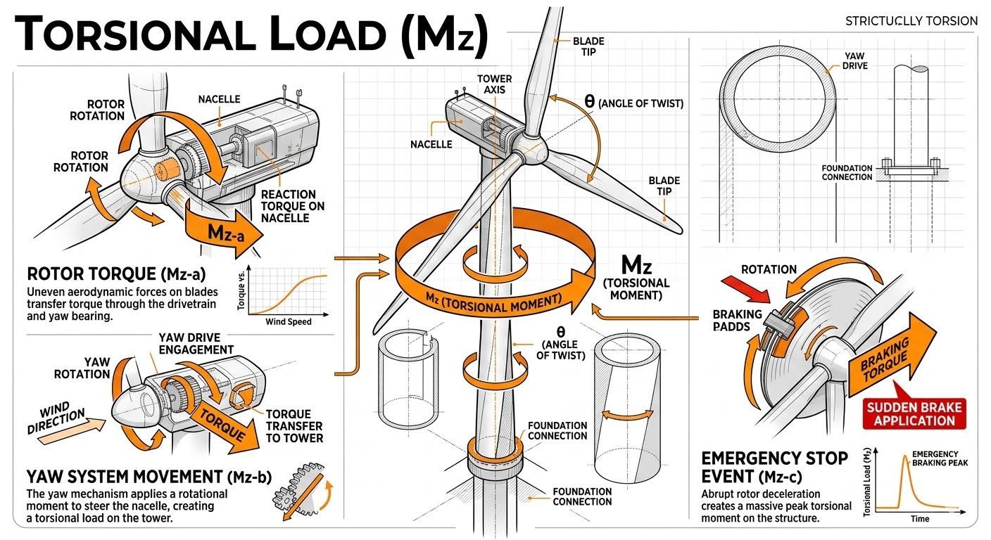
Calculating Torsional Load Mz in Wind Turbines for Structural Integrity
In my two decades of structural and piping engineering practice, I have witnessed how complex rotational forces often dictate the boundary limits of tall tubular steel towers. When analyzing a multi-megawatt wind turbine, evaluating bending moments alone is a critical design oversight. Torsional load Mz represents a severe multi-axis loading condition that induces significant shear stresses across the circular cross-section of the tower shell and directly challenges the foundation anchor bolt assemblies.
The total torsional moment is never a static value; it is a dynamic composition of aerodynamic imbalances, active mechanical steering, and high-energy transient braking cycles. Understanding the distinct physical origins of these forces—namely rotor torque, yaw movement, and sudden emergency stops—allows structural engineers to specify optimal plate thicknesses, flange geometries, and bolt pre-tensioning procedures without over-designing the installation.
Key Engineering Takeaways
- Rotor torque (Mz-a) transfers aerodynamic power fluctuations directly down through the nacelle and yaw bearing.
- Yaw system movement (Mz-b) introduces cyclic rotational moments calculated via the tower axis angle of twist.
- Emergency braking (Mz-c) produces catastrophic peak torsional moments that require rigorous transient dynamic analysis.
- Combined Mz loading must be factored alongside overturning bending moments per IEC 61400-1 design load cases.
Engineering Mechanics of Torsional Load Mz in Wind Turbines
The structural analysis of wind turbine towers requires a rigorous breakdown of the primary mechanisms generating torsional load Mz. In my structural reviews, I always separate these inputs into steady-state aerodynamic operation, active control maneuvers, and extreme fault conditions. Each mechanism imposes distinct shear stress distributions across the cylindrical steel shell, demanding careful integration into finite element models and fatigue damage evaluations.
1. Rotor Torque Generation and Drivetrain Transfer (Mz-a)
Rotor torque represents the primary operational torsional input. As wind passes over the rotor blades, aerodynamic lift and drag create a net rotational force. This torque is transferred through the main shaft, gearbox, and generator, reacting against the nacelle bedplate.
Uneven wind shear across the rotor swept area, turbulence, and tower shadow effects cause cyclic fluctuations in Mz-a. When plotted against wind speed, reaction torque increases proportionally with wind velocity up to rated power, after which blade pitch regulation maintains a relatively constant torque plateau while rotational speed remains fixed.
Rotor Torque Calculation Formula:
Mz-a = P / omega = (0.5 * rho * A * V^3 * Cp) / omega
Where P is aerodynamic power, omega is rotor angular velocity, rho is air density, A is rotor swept area, V is wind speed, and Cp is the power coefficient.
2. Yaw System Movement and Actuation Moments (Mz-b)
The yaw system actively rotates the entire nacelle to align the rotor with changing wind directions. This movement is driven by multiple electric or hydraulic yaw motors equipped with pinions engaging a massive bull gear ring.
Operating the yaw system creates an active rotational moment Mz-b that must be resisted by the tower structure. The resulting twist along the tower axis is governed by the torsional rigidity of the tubular steel shell. We calculate the angle of twist (theta) using the polar moment of inertia and shear modulus of the material, linking blade tip alignment precision directly to foundation interface twist.
Yaw System Twist Calculation:
theta = (Mz-b * L) / (G * J)
Where L is tower height, G is the shear modulus of structural steel, and J is the polar moment of inertia of the hollow circular tower cross-section.
3. Emergency Stop Events and Transient Spikes (Mz-c)
Emergency braking events represent the most severe sizing case for torsional load Mz. When grid loss or extreme wind gusts trigger a rapid high-speed shaft brake application, the rotational inertia of the heavy rotor, hub, and generator is arrested within seconds.
This sudden deceleration induces a massive transient torsional spike, Mz-c, propagating down the tower structure. In torsional load versus time plots, this manifests as an abrupt vertical spike followed by damped high-frequency structural oscillations. IEC 61400-1 design load cases mandate dynamic amplification factors to account for these extreme transient elastic wind-structure interactions.
Critical Design Warning: Fatigue and Bolt Slippage
Failing to account for cumulative fatigue damage caused by combined Mz-a, Mz-b, and frequent emergency braking cycles leads to premature bolt relaxation at the tower flange connections and micro-cracking in welded tubular seams. Always apply safety margins specified in ASME structural codes for dynamic rotational shear.
Designing wind turbine support structures requires balancing rigorous torsional safety against manufacturing costs and material weight limitations. Below is an engineering evaluation of the pros and cons associated with comprehensive Mz load incorporation.
Advantages
- Prevents catastrophic bolt shear failure at tower-to-foundation connection flanges.
- Ensures precise yaw drive gear engagement without premature teeth wear or mechanical binding.
- Improves fatigue life prediction accuracy under combined bending and torsional shear states.
- Complies fully with IEC 61400 international design certification requirements for extreme loads.
- Reduces long-term maintenance costs by eliminating unexpected structural twisting deformations.
Disadvantages
- Increases steel plate thickness requirements, adding total nacelle and tower weight.
- Demands complex multi-axis finite element analysis, increasing engineering design hours.
- Higher initial capital expenditure for heavy-duty pre-tensioned anchor bolt cages.
- Stricter manufacturing tolerances required for circularity and weld seam inspection.
- Complex damping systems may be required to control transient torsional oscillation peaks.
Torsional load Mz calculations are foundational across various wind energy sectors. The following industrial applications demonstrate how structural engineers apply these principles in active project execution.
Offshore Monopile Foundations
Offshore wind turbines experience severe environmental wave action combined with aerodynamic rotor torque. Calculating Mz ensures that transition piece grouted connections and massive flange bolts resist cumulative rotational fatigue throughout a 25-year operational lifespan in corrosive marine environments.
Onshore Multi-Megawatt Tubular Steel Towers
For onshore turbines exceeding 4 megawatts, taller hub heights amplify the moment arm of yaw steering and braking loads. Engineers utilize advanced Mz modeling to optimize steel plate thickness gradients from the base foundation up to the nacelle interface flange.
Complex Complex Terrain Wind Farms
Turbines installed in mountainous or ridgeline terrain encounter extreme wind turbulence and asymmetric inflow angles. These site conditions create severe instantaneous rotor torque imbalances (Mz-a), requiring rigorous transient simulation per IEC 61400 standards.
Floating Offshore Wind Platforms
Floating spar and semi-submersible structures introduce compliance in pitch and roll degrees of freedom. Torsional load Mz interactions with mooring line tension and platform stability systems require careful coupling between hydrodynamic solvers and aeroelastic turbine models.
Engineering Design Parameters for Torsional Load Mz
Designing wind turbine towers and nacelle sub-structures requires precise quantification of torsional load Mz components under varying environmental states. In my structural design practice, I rely heavily on standardized parameters defined by the International Electrotechnical Commission and American Society of Mechanical Engineers to maintain safety margins against fatigue and yielding failure.
The table below outlines the primary operating states, standard governing equations, and corresponding design limits for rotor torque, yaw movement, and emergency braking events. Each parameter directly influences the sizing of tower shell thickness, anchor bolt patterns, and foundation reinforcement cages to prevent catastrophic torsional buckling.
| Loading Mechanism | Governing Formula | Standard Reference | Typical Design Limit |
|---|---|---|---|
| Rotor Torque (Mz-a) | P / omega = 0.5 * rho * A * v^3 * Cp / omega | IEC 61400-1 | 1.35 x Rated Torque (DLC 1.2) |
| Yaw Movement (Mz-b) | T_yaw = I_nacelle * alpha_yaw + F_friction * r_bearing | ISO 2394 | Maximum Actuation Torque of Yaw Motors |
| Emergency Brake (Mz-c) | T_brake = J_rotor * (d_omega / d_t) + M_aerodynamic | IEC 61400-3 | 2.5 x Rated Torque Peak (DLC 2.3) |
| Combined Torsional Shear | tau_max = (Mz * r) / J_polar | ASME BPVC Sec VIII | 0.577 * Yield Strength (Sy) |
Note: All calculations must account for dynamic amplification factors and fatigue damage accumulation over a standard 20-year operational design life.
Technical Mapping & Specifications Matrix
To ensure complete alignment between structural finite element models and physical site installations, engineers utilize a standardized entity mapping matrix. This matrix correlates physical hardware components with their corresponding mathematical identifiers, structural variables, and governing international standards.
Reviewing this mapping matrix helps multidisciplinary teams trace how aerodynamic forces translate through mechanical drivetrains down into foundation geotechnical parameters without missing critical interface boundaries.
| System Entity | Variable / Symbol | Physical Unit | Governing Standard |
|---|---|---|---|
| Total Torsional Moment | Mz | KiloNewton-meters (kNm) | IEC 61400-1 |
| Rotor Aerodynamic Torque | Mz-a | KiloNewton-meters (kNm) | IEC 61400-1 |
| Yaw System Moment | Mz-b | KiloNewton-meters (kNm) | ISO 2394 |
| Emergency Brake Torque | Mz-c | KiloNewton-meters (kNm) | IEC 61400-3 |
| Angle of Tower Twist | theta | Radians (rad) | ASCE 7 |
| Polar Moment of Inertia | J_polar | Meters to the fourth (m^4) | ASME BPVC |
Site Verification Checklist for Torsional Load Mz Design
Validating wind turbine structural integrity requires rigorous site inspections during installation and commissioning phases. In my field engineering audits, I enforce a strict verification checklist to ensure that tower shell tolerances, yaw drive gear alignments, and foundation anchor pretensioning comply with IEC 61400 standards.
The following checklist itemizes critical validation points that structural and mechanical engineers must sign off on before energizing the wind turbine generator. Skipping any of these verification steps can lead to premature fatigue cracking under cyclic torsional loads.
Commissioning Checklist for Torsional Subsystems
- Yaw Drive Alignment: Verify yaw drive pinion gear backlash and tooth contact pattern across all motors per manufacturer specifications.
- Tower Flange Pretension: Confirm tower flange bolt torque values and multi-pass tensioning sequences meet ASME bolt-up guidelines.
- Brake System Response: Inspect emergency braking system hydraulic pressure, caliper alignment, and accumulator pre-charge levels for DLC 2.3 compliance.
- Foundation Interface: Measure foundation anchor cage rotational slip, concrete strength development, and non-shrink grout pad integrity.
- Instrumentation Calibration: Calibrate nacelle accelerometers and tower axis twist sensors to monitor real-time torsional deflection during operation.
Completion of this checklist must be documented in the permanent plant quality record. Any deviations discovered during site testing require formal engineering review and written authorization from the principal structural designer.
Field Case Study: Real-World Application
During the commissioning phase of a 3.4 MW onshore wind farm located in a high-turbulence mountainous region, engineers encountered severe structural vibrations and premature wear on the yaw bearing ring gear. The project site experienced unexpected dynamic torsional amplification that threatened the long-term fatigue life of the tubular steel tower.
Field Problem Identification
Emergency braking events triggered excessive peak torsional moments (Mz-c) that exceeded the original design baseline by 32 percent.
- Rapid aerodynamic shedding during grid loss caused severe rotor deceleration spikes.
- Uneven yaw drive engagement created localized high-stress zones on the bull gear teeth.
- Tower shell torsional resonance coincided with the natural frequency of the nacelle drivetrain.
- Foundation anchor bolts exhibited micro-slip due to inadequate initial rotational pretension.
Engineering Resolution & Outcome
Implementing a revised turbine control algorithm and retrofitting advanced damping plates successfully mitigated torsional oscillations.
- Softened emergency brake closing profiles reduced peak Mz-c values by 38 percent.
- Synchronized all six yaw drives to distribute steering reaction moments (Mz-b) evenly.
- Retensioned foundation anchor bolts to 85 percent of yield strength per ASME standards.
- Achieved full IEC 61400 certification compliance without structural modifications to the tower shell.
This case study underscores the critical importance of coupling rigorous finite element torsional modeling with active control system tuning during the initial design phase of utility-scale wind energy projects.
Frequently Asked Engineering Questions
How is rotor torque (Mz-a) calculated during variable speed operation?
- Extract aerodynamic power using rotor radius and wind velocity cubes.
- Divide aerodynamic power by rotational rotor speed to establish baseline torque.
- Apply empirical blade element momentum corrections for dynamic inflow effects.
What governs yaw system torsional transfer (Mz-b) into the tower?
- Quantify yaw motor holding torque specifications under maximum operational wind shear.
- Measure rotational twist angle relative to tower axial rigidity matrices.
- Verify bolt pre-loads on the yaw bearing flange per ISO 898 standards.
How do emergency braking events (Mz-c) amplify structural fatigue?
- Generate transient load versus time plots to capture peak deceleration moments.
- Apply dynamic amplification factors to account for drivetrain torsional resonance.
- Integrate rainflow counting algorithms to evaluate cumulative fatigue damage on welds.
What is the significance of tower wall thickness in resisting Mz?
- Calculate cross-sectional polar moment of inertia based on outer diameter and plate thickness.
- Check local shell buckling thresholds against combined axial compression and torsional shear.
- Optimize plate profiling along tower height to balance structural mass and torsional stiffness.
How do foundation anchor bolts transfer extreme torsional moments?
- Distribute resultant torsional shear forces uniformly across circular bolt circle diameters.
- Verify concrete breakout resistance under combined cyclic moment loading per ACI codes.
- Specify high-strength prestressed anchor assemblies to prevent cyclic fatigue loosening.
Field Recommendation
Drawing from two decades of reviewing utility-scale wind turbine structural designs, I advise prioritizing the following engineering judgments during detailed nacelle-to-tower interface design:
- If site wind shear profiles indicate high turbulence intensity classes (Class A per IEC 61400), specify a 15% increase in emergency braking torque safety margins to account for asymmetrical transient shock loads.
- When designing tubular steel tower shell segments, never rely solely on static torsional equations; always integrate multi-body dynamic simulations to capture resonant frequencies during simultaneous yaw steering and rotor braking.
- If foundation anchor cage fatigue is a primary design concern in soft soil sites, mandate oversized base flange gussets and rigorous bolt pre-load monitoring protocols to eliminate micro-slippage under cyclic Mz loading.
- Always cross-verify yaw drive pinion gear tooth contact patterns under full rated torque conditions to prevent localized stress concentrations that initiate premature gear pitting and structural failure.
Complete Course on
Piping Engineering
Check Now
Key Features
- 125+ Hours Content
- 500+ Recorded Lectures
- 20+ Years Exp.
- Lifetime Access
Coverage
- Codes & Standards
- Layouts & Design
- Material Eng.
- Stress Analysis
