Wind Turbine Rotor Blade and Hub Assembly Engineering Design
In my two decades of industrial mechanical and structural engineering practice, few assemblies demand as relentless a combination of static strength, dynamic fatigue resistance, and precision alignment as the rotor blade and hub assembly of utility-scale wind turbines. When evaluating multi-megawatt systems, I find that the structural integrity of the entire machine hinges upon how effectively kinetic energy captured by composite blades is transmitted through the central hub casting, into the nacelle, and down the tower foundation.
Operating in hostile atmospheric environments, these assemblies experience severe wind shear, turbulence intensity variations, and centrifugal stresses that test the limits of modern metallurgy and composite science. Designing these critical load paths requires strict adherence to international design codes such as ISO and ASME guidelines to prevent catastrophic structural failure.
Key Engineering Takeaways
- Blade-to-hub pitch bearing connections transmit high bending moments and dynamic thrust loads.
- Ductile iron or cast steel hub castings require rigorous non-destructive testing for internal casting defects.
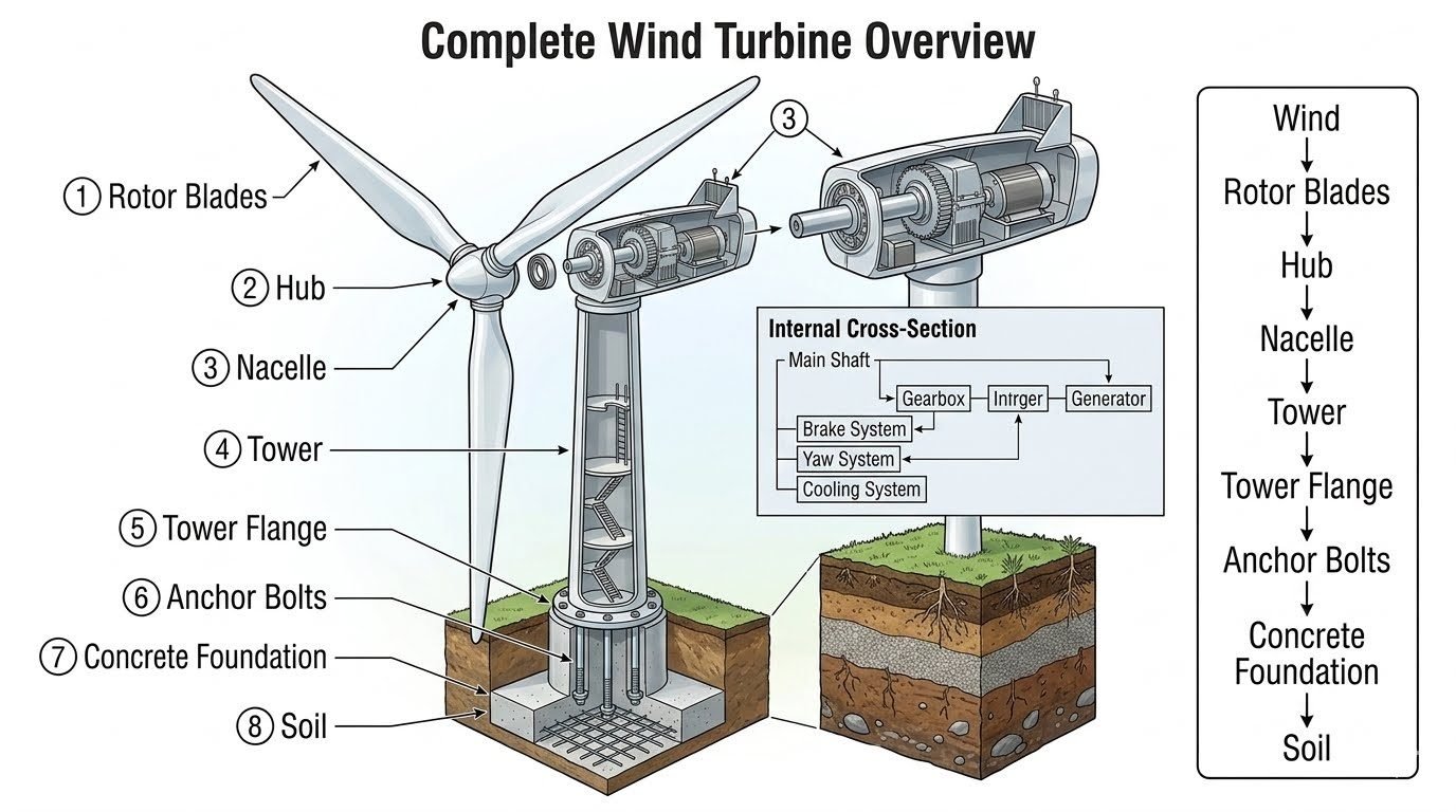
- Load transfer cascades continuously from rotor blades, through the hub, nacelle, and tower, down to anchor bolts and concrete foundations.
- Fatigue damage accumulation must be calculated using long-term wind distribution histograms and Miner’s rule.
Rotor Blade and Hub Assembly Structural Mechanics
Assembly structural mechanics: The analytical evaluation of aerodynamic thrust, centrifugal forces, gravitational dead loads, and gyroscopic moments acting on wind turbine rotor blades and their structural attachment points at the hub casting.
The engineering of a modern wind turbine begins at the outermost boundary of the rotor blades and extends all the way down to the soil mechanics of the foundation. As wind flows across the airfoil profile of the rotor blades, it generates both lift and drag forces. These aerodynamic forces create a massive thrust load acting parallel to the rotor axis, combined with flapwise and edgewise bending moments that vary cyclically with every revolution due to wind shear and tower shadow effects.
To transfer these complex loads safely, the rotor blades are bolted directly to high-capacity pitch bearings mounted on the perimeter of the main hub casting. In my structural design reviews, I emphasize that the root section of the composite blade—typically constructed from multiaxial fiberglass or carbon-epoxy laminates embedded with heavy steel T-bolts or bonded studs—represents one of the most critical stress concentration zones in the entire machine.
Hub Casting Metallurgy and Stress Distribution
The hub casting itself serves as the mechanical heart of the rotor system. Typically manufactured from high-grade spheroidal graphite cast iron (ductile iron such as EN-GJS-400-18U or EN-GJS-350-RT), the hub must exhibit exceptional fracture toughness and low-temperature impact resistance. The geometric complexity of the hub—featuring massive flange faces for blade attachment and a central bore flange for mounting to the main shaft—creates severe casting thermal gradients and residual stresses.
During operation, centrifugal forces pull outward on each blade at magnitudes exceeding several hundred metric tons per blade in 5 MW+ turbines. This tension creates high tensile hoop stresses around the blade connection studs. Simultaneously, the aerodynamic bending moments subject opposing sides of the hub flange to alternating tension and compression cycles. Engineers must apply finite element analysis (FEA) models to evaluate stress concentrations at fillet radii and bolt hole margins, ensuring safety factors comply strictly with IEC 61400-1 design requirements.
Critical Design Warning: Flange Distortion and Bolt Preload Loss
Failure to maintain precise bolt preload across large-diameter blade connection flanges leads directly to micro-gapping under cyclic bending moments. Once gapping occurs, cyclic shear loads transfer directly to the studs, causing progressive fatigue failure, fretting corrosion, and catastrophic bolt shear. Ultrasonic bolt elongation verification must be performed during assembly.
Nacelle Mechanical Integration and Power Train Load Path
Once mechanical energy passes through the hub, it enters the nacelle housing. The hub is rigidly bolted to the main shaft (or low-speed shaft), which is supported by heavy-duty main bearings mounted to the nacelle bedplate. In standard geared configurations, the main shaft transmits torque through a multi-stage planetary and helical gearbox to step up rotational speed before driving the high-speed generator.
The nacelle also houses the yaw system—consisting of massive active yaw gears and friction brakes—which rotates the entire nacelle atop the tower to face the prevailing wind direction. Separate mechanical disc brake systems mounted on the high-speed shaft provide emergency stopping capability independent of full-span aerodynamic blade feathering. All internal components are engineered to isolate vibrational harmonics and prevent resonance with the natural frequency of the tubular steel or concrete tower.
Global Structural Hierarchy and Foundation Load Transfer
The ultimate test of wind turbine engineering is the uninterrupted load transfer path down to the earth. The component hierarchy functions as a continuous structural chain:
- Wind & Rotor Blades: Capture kinetic energy and transform it into torque and thrust.
- Hub & Nacelle: House mechanical drives, bearings, braking systems, and yaw control mechanisms.
- Tower & Tower Flange: Provide elevated vertical support while resisting monumental overturning bending moments.
- Anchor Bolts & Concrete Foundation: Transfer massive shear forces and overturning moments into the supporting soil matrix.
The foundation design—whether a gravity-base octagonal concrete slab or a deeply piled rock-anchor configuration—must suppress differential settlement. Any tilt in the foundation magnifies static eccentricity at the tower base, dramatically accelerating fatigue damage in the rotor and hub assembly above.
System trade-offs: Evaluating the structural advantages and mechanical limitations of modular wind turbine rotor and nacelle configurations under variable operational constraints.
Advantages
- High power-to-weight efficiency achieved through advanced composite blade engineering.
- Ductile iron hub castings provide superior vibration damping and impact resistance compared to welded fabrications.
- Modular nacelle layout allows discrete maintenance and replacement of gearboxes and generators.
- Robust pitch control mechanisms enable precise aerodynamic braking and optimal energy capture across wind speeds.
- Standardized flange connections simplify heavy crane lifting and offshore installation sequences.
Disadvantages
- Severe susceptibility to cyclic fatigue and micro-cracking in thick composite blade root laminates.
- Complex casting geometry introduces risks of internal microporosity and residual thermal stresses.
- High sensitivity to bolt preload relaxation at blade-to-hub and tower flange connections.
- Significant logistical challenges in transporting oversized multi-megawatt rotor blades and heavy hub castings.
- High dynamic magnification factors require continuous online condition monitoring to prevent unexpected catastrophic failure.
Industrial deployment sectors: Examining how rotor blade and hub assembly principles are applied across diverse onshore and offshore power generation environments.
Onshore Utility-Scale Wind Farms
Deployed across flat plains and ridge lines, multi-megawatt onshore turbines utilize advanced carbon-fiber reinforced rotor blades and ductile iron hubs. These installations require rugged yaw and braking systems capable of operating reliably in extreme ambient temperature ranges from sub-zero winters to scorching summer deserts.
Offshore Fixed-Bottom Wind Turbines
Offshore marine environments impose severe corrosive and hydrodynamic forces on the entire structural hierarchy. Hub castings and blade root fasteners receive specialized epoxy coatings and cathodic protection to withstand salt spray, while massive monopile foundations anchor the tower against relentless wave action and wind shear.
Floating Offshore Wind Installations
Floating platforms introduce six degrees of rotational and translational motion, creating complex gyroscopic loads on the rotor blade and hub assembly. Structural engineers must account for platform pitch and roll, which dynamically alter aerodynamic inflow angles and accelerate fatigue accumulation in the main shaft bearings.
Remote Microgrid Wind Systems
Isolated island and remote industrial microgrids rely on highly reliable mid-scale wind turbines. In these settings, robust hub mechanical designs and simplified hydraulic or electric pitching mechanisms ensure continuous power generation with minimal scheduled maintenance requirements over extended service intervals.
Rotor Blade and Hub Interface Specifications
Interface Design Parameters: The structural and mechanical specifications governing the connection between the rotor blade root and the cast steel hub, ensuring compliance with IEC 61400-1 load cases.
In my experience, the interface between the rotor blade and the cast hub represents one of the most highly stressed mechanical joints in the entire wind turbine structure. This connection must withstand extreme aerodynamic thrust, gravitational bending moments, and dynamic fatigue cycles over a 20-to-25-year operational lifetime. We typically utilize high-strength prestressed T-bolts or embedded sleeves to secure the composite blade root to the ductile iron hub casting.
To ensure structural integrity under extreme wind conditions, designers must carefully calculate the bolt pre-tensioning forces. If the pre-tension is too low, the joint will experience separation and rapid fatigue failure; if it is too high, the bolts can yield during peak aerodynamic gusts. The table below outlines the critical engineering parameters I evaluate during the design verification phase of utility-scale wind turbine rotor assemblies.
| Parameter | Unit | Value Range (Typical 3MW-5MW) | Design Standard / Reference | Engineering Significance |
|---|---|---|---|---|
| Blade Root Diameter | mm | 2300 – 3200 | IEC 61400-1 | Dictates the spatial distribution of connection bolts. |
| Bolt Grade | Class | 10.9 / 12.9 | ISO 898-1 | High tensile strength required to resist cyclic fatigue. |
| Pre-tension Level | % of Yield | 70 – 80 | VDI 2230 | Prevents joint separation under maximum bending moments. |
| Hub Material | Grade | EN-GJS-400-18U-LT | EN 1563 | Ductile iron with high low-temperature impact toughness. |
| Blade Root Bending Moment | kNm | 15000 – 35000 | GL 2010 Guidelines | Primary design load for sizing the pitch bearing and bolts. |
A key takeaway from my field inspections is that maintaining the specified bolt pre-tension during the first 500 hours of operation is vital to preventing premature joint failure.
Technical Mapping & Specifications Matrix
Component Load Path Mapping: The systematic tracking of structural forces from the aerodynamic surfaces of the rotor blades through the mechanical drivetrain to the foundation.
When analyzing the structural integrity of a wind turbine, I trace the load path from the aerodynamic capture point down to the soil interface. Each component in this hierarchy plays a distinct role in either converting kinetic energy or transferring massive static and dynamic forces. Mapping these physical entities alongside their primary load types and governing design standards is a fundamental step in our structural verification workflow.
This matrix serves as a cross-reference tool for systems engineers to verify that every mechanical interface is designed to the correct code. By aligning the rotor blade, hub, main shaft, and tower flanges with their respective stress profiles, we can identify potential stiffness mismatches that might lead to localized stress concentrations.
| Component Entity | Primary Material | Dominant Load Type | Governing Standard | Primary Structural Role |
|---|---|---|---|---|
| Rotor Blade | Composite (GFRP/CFRP) | Aerodynamic Lift, Bending | DNV-ST-0376 | Captures wind energy; experiences high cyclic fatigue. |
| Rotor Hub | Cast Ductile Iron | Centrifugal, Bending | IEC 61400-1 | Houses pitch bearings; transfers blade loads to main shaft. |
| Main Shaft | Forged Alloy Steel (34CrNiMo6) | Torsion, Shear | ASME PTC 11 | Transmits rotational torque to the gearbox assembly. |
| Nacelle Bedplate | Cast Iron / Welded Steel | Structural Weight, Torque | Eurocode 3 | Supports the drivetrain; maintains shaft alignment. |
| Tower Flange | Forged Structural Steel | Tension, Compression | EN 1090-2 | Connects tower segments; transfers overturning moments. |
Rotor and Hub Assembly Site Verification Checklist
Field Quality Control Protocol: The mandatory inspection and testing steps required during the mechanical assembly of the rotor blades and hub to ensure design compliance.
In my years supervising wind turbine installations, the day we lift and bolt the rotor assembly is always the most critical. The field environment is vastly different from a controlled factory floor. Wind gusts, dust, and temperature fluctuations can severely impact the accuracy of bolt tensioning and joint sealing. Therefore, a rigorous, step-by-step site verification protocol is non-negotiable to prevent catastrophic failures during commissioning.
Before the rotor is lifted, the installation team must verify that all contact surfaces are completely free of grease, rust, and debris. Any contamination on the flange faces can reduce the friction coefficient, leading to micro-slippage and subsequent bolt loosening. Additionally, hydraulic torque wrenches and tensioning jacks must have valid calibration certificates.
The checklist below represents the minimum field verification steps I require before signing off on a rotor-to-hub assembly. Each step must be documented with digital photographs and torque log sheets.
-
Blade Root Flange Inspection Verify flatness of the composite blade root flange using a dial indicator (maximum deviation must be less than 0.2 mm).
-
T-Bolt Pre-Load Verification Confirm that hydraulic tensioning pressures match the design values specified in VDI 2230.
-
Pitch Bearing Seal Integrity Inspect the polyurethane seals for any signs of extrusion or damage during blade insertion.
-
Electrical Bonding and Grounding Measure the electrical resistance across the blade-to-hub lightning protection system (must be less than 0.01 Ohms).
-
Yaw and Pitch Drive Backlash Check the gear mesh backlash between the pitch drive pinion and the internal gear ring using feeler gauges.
-
Lubrication System Charge Verify that the automatic grease dispensing system for the pitch bearing is fully primed and free of air pockets.
Field Case Study: Real-World Application
Root Cause Analysis: The forensic engineering investigation of a premature blade-to-hub connection failure and the subsequent structural remediation.
During a routine maintenance campaign at a 150 MW wind farm in a high-wind coastal region, our technicians discovered several fractured T-bolts on the blade-to-hub connection of a 3.2 MW turbine. The turbine had been in operation for less than three years, far short of its 20-year design life. I was brought in to lead the forensic engineering investigation, identify the root cause of the failures, and implement a robust remediation strategy to prevent a catastrophic rotor loss.
Our initial inspection revealed that the failures were concentrated on the windward side of the blade root during peak aerodynamic thrust. This indicated that the joint was experiencing cyclic tension that exceeded the fatigue limit of the Class 10.9 bolts. We collected bolt fragments for metallurgical analysis and reviewed the original installation torque logs to reconstruct the assembly history.
The investigation identified a combination of installation errors and environmental factors that led to joint degradation:
- Inconsistent hydraulic tensioning during field assembly, resulting in some bolts having only 50% of their specified pre-load.
- Micro-slippage at the composite-to-steel interface due to paint overspray on the mating surfaces.
- High cyclic aerodynamic loads from localized wind shear that exceeded the design fatigue envelope of the under-tensioned bolts.
- Rapid propagation of fatigue cracks starting from the first engaged thread of the T-bolts.
By implementing a comprehensive engineering redesign and strict field protocols, we achieved the following measurable results:
- Replaced all Class 10.9 T-bolts with high-fatigue-resistant Class 12.9 bolts featuring a specialized anti-corrosion coating.
- Mandated the complete removal of paint and primer from the flange mating faces to achieve a friction coefficient of at least 0.4.
- Introduced a two-stage hydraulic tensioning procedure with a 10% over-tension allowance to compensate for short-term relaxation.
- Established a mandatory ultrasonic testing schedule for all blade root bolts at 500-hour and 2000-hour operational intervals.
- Zero bolt failures have been recorded across the entire wind farm in the five years following the remediation.
Based on this experience, I highly recommend that wind farm operators never rely solely on torque-control methods for critical structural joints. Hydraulic tensioning, combined with ultrasonic elongation measurement, is the only reliable way to guarantee that the design pre-load is actually achieved in the field.
Frequently Asked Engineering Questions
What materials are predominantly utilized for modern wind turbine rotor blade and hub casting manufacturing?
- Rotor blades utilize E-glass or carbon fiber reinforced polymers (CFRP) embedded in epoxy or polyester matrices.
- Hub castings are manufactured from ductile cast iron (such as EN-GJS-400-18U or ASTM A395) for sub-zero impact toughness.
- Internal spars incorporate balsa wood or structural PVC foam core sandwiches to maximize bending stiffness without weight penalties.
How do dynamic load transfers occur from the rotating blades down through the tower foundation?
- Aerodynamic forces act upon the rotor blades, inducing massive flapwise and edgewise bending moments.
- Moments transfer through the hub casting, main shaft, and nacelle bedplate into the yaw bearing interface.
- The tubular steel or concrete tower channels these overturning moments down to the base tower flange and high-strength anchor bolts.
- Finally, the reinforced concrete gravity or pile-cap foundation dissipates the loads safely into the surrounding soil.
What mechanical protection mechanisms safeguard the nacelle internal assembly during extreme wind gusts?
- Pitch control systems feather the rotor blades into the wind to rapidly dump aerodynamic lift.
- High-speed shaft mechanical disc brakes engage to lock the drivetrain during maintenance or emergency shutdowns.
- Active yaw motors rotate the nacelle to align orthogonally with shifting wind vectors, minimizing gyroscopic fatigue.
Why are multi-stage gearboxes frequently paired with generators in utility-scale wind turbine nacelles?
- Large rotors operate at low speeds (8 to 20 RPM), which are unsuitable for direct electrical generation without massive pole counts.
- Planetary and helical gearboxes step up shaft speeds to 1,500 or 1,800 RPM for compact, cost-effective generators.
- While direct-drive turbines eliminate gearboxes, geared configurations remain favored for overall nacelle weight reduction in onshore logistics.
What non-destructive examination methods verify the structural integrity of tower flange anchor bolts?
- Ultrasonic testing (UT) detects subsurface stress corrosion cracking and micro-voids along the bolt shank.
- Calibrated torque wrench checks verify that preload tension meets stringent structural engineering specifications.
- Magnetic particle inspection (MPI) identifies surface-breaking fatigue fissures on exposed threaded sections and flange rings.
Field Recommendation
Drawing upon two decades of structural and mechanical machinery oversight, I advise implementing the following decisive engineering actions during the design, procurement, and erection phases of utility-scale wind turbine projects:
- If your site experiences high turbulence intensity and extreme wind shear, select carbon-fiber spar caps over standard E-glass blades to restrict tip deflection and prevent tower-strike clearances.
- When specifying hub castings, enforce strict Charpy V-notch impact testing at minus 20 degrees Celsius, regardless of local climate, to prevent brittle fracture under unexpected dynamic loading.
- On tower flange connections, mandate hydraulic tensioning over standard torque wrench tightening for all anchor bolts to eliminate friction errors and guarantee uniform clamping preload across the ring.
- For nacelle internal machinery, prioritize closed-loop glycol cooling systems with redundancy pumps, as thermal degradation remains the leading root cause of premature gearbox bearing failure.
- During commissioning, execute a complete modal analysis of the assembled tower and rotor system to verify that natural frequencies avoid harmonic excitation bands driven by blade passing frequencies.
Complete Course on
Piping Engineering
Check Now
Key Features
- 125+ Hours Content
- 500+ Recorded Lectures
- 20+ Years Exp.
- Lifetime Access
Coverage
- Codes & Standards
- Layouts & Design
- Material Eng.
- Stress Analysis
