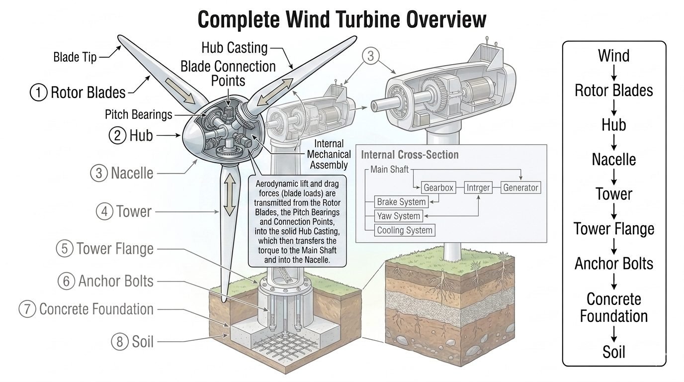
Rotor Blade Aerodynamic Loads and Torque Transmission Mechanisms
In my two decades navigating complex mechanical and structural systems, I have continually observed that wind turbine longevity depends entirely on understanding transient aerodynamic forces. When high-velocity air masses impact utility-scale rotor blades, they induce profound lift and drag vectors across the aerodynamic span. These forces do not simply dissipate; they concentrate intensely at the blade roots, generating complex bending moments, axial thrust loads, and torsional twisting moments that must be managed flawlessly by the mechanical drivetrain.
Tracing this mechanical load path reveals an intricate journey from fluid dynamics to solid mechanics. The forces originate across composite blade surfaces, travel through massive slewing rings, cross robust cast nodes, and ultimately convert into usable rotational torque at the main shaft. Engineers designing these systems must adhere to strict international frameworks, including IEC 61400 standards for wind turbine design and ISO gear and bearing standards, ensuring structural integrity over twenty-year operational lifecycles.
Key Engineering Takeaways
- Aerodynamic lift and drag forces act as the primary ignition source for mechanical torque generation in modern wind energy systems.
- Pitch bearings endure severe combined bending and axial loads while actively modulating the angle of attack to optimize power output.
- Hub castings act as critical structural bridges, dampening high-frequency vibrations before torque reaches the low-speed main shaft.
Rotor Blade Aerodynamic Loads and Structural Load Paths
The conversion of kinetic wind energy into electrical power begins at the blade tip and progresses inward toward the nacelle. As wind flows over the airfoil profile, pressure differentials generate lift perpendicular to the relative wind and drag parallel to it. In utility-scale turbines featuring rotor diameters exceeding 150 meters, these distributed aerodynamic pressures create colossal flapping and edgewise bending moments. The magnitude of these forces scales with the square of the apparent wind velocity, making peak gust events critical sizing criteria for every downstream mechanical component.
To quantify these forces, engineers utilize blade element momentum theory combined with computational fluid dynamics simulations. The resulting aerodynamic thrust force (F_t) and torque (T) drive the primary design envelope for the rotor assembly.
T = 0.5 * rho * A * R * V^2 * C_q
Where rho represents air density, A is the swept rotor area, V is the wind velocity, C_t is the thrust coefficient, C_q is the torque coefficient, and R is the rotor radius. These equations illustrate why precise control over the aerodynamic coefficients is non-negotiable during extreme weather transients.
Once generated across the blade span, these immense aerodynamic loads concentrate at the blade root connection studs. Here, high-strength steel T-bolts or embedded stud matrices anchor the composite blade to the outer raceway of the pitch bearing. The pitch bearing itself is a massive slewing ring, typically a four-point contact ball bearing or a double-row roller bearing. It must sustain high axial tension, compression, and tilting moments simultaneously while allowing precise rotational movement driven by electric or hydraulic pitch motors.
Critical Design Warning: Pitch Bearing Raceway Brinelling
Under stationary park conditions or continuous low-amplitude vibrations from wind turbulence, pitch bearings are susceptible to false brinelling. Roller elements create micro-indentations in the raceway if lubrication films fail. Engineers must incorporate automated centralized grease injection systems and execute periodic small-angle slewing sweeps to distribute lubricant and prevent catastrophic bearing seizure under high operational loads.
Passing through the pitch bearing inner ring, the aerodynamic loads enter the solid hub casting. The hub casting serves as the central mechanical nexus of the rotor. Typically fabricated from nodular cast iron (such as GGG-40.3 or GGG-70 according to DIN EN 1563 standards), the hub must possess exceptional fracture toughness and fatigue resistance to withstand millions of cyclical load reversals. The geometry of the hub is optimized using finite element analysis to eliminate stress concentration notches, especially around the large window openings where pitch drives are mounted.
Within the hub casting, the individual blade loads merge into a combined rotational torque vector. This torque is transmitted directly to the forged steel main shaft via a high-capacity interference fit or heavy-duty flanged bolted connection. The main shaft transfers this mechanical energy out of the rotating rotor hub and into the stationary nacelle environment, traversing main support bearings that constrain radial and axial displacements.
To ensure compliance with international safety codes, designers evaluate these load paths against stringent ultimate limit state and fatigue limit state criteria outlined in IEC 61400-1. Fatigue damage accumulation is calculated using Palmgren-Miner linear damage hypotheses, integrating rainflow-counted stress spectra gathered from multi-axial strain gauges installed during prototype field testing. Any misalignment in the load path between the pitch bearing and hub mounting flange introduces severe bending moments into the main shaft, drastically reducing bearing fatigue life.
Engineering Advantages
- Active pitch bearing control optimizes the angle of attack, maximizing energy capture across variable wind speeds.
- Robust nodular cast iron hubs provide exceptional damping capacity for high-frequency aerodynamic shock loads.
- Direct mechanical load paths eliminate intermediary energy conversion losses between the rotor and main shaft.
- Redundant multi-bolt flange connections simplify modular assembly and scheduled offshore maintenance overhauls.
- Standardized design methodologies under international codes ensure predictable structural fatigue performance.
Engineering Disadvantages
- Pitch bearings endure severe combined axial and moment loads, making them prone to premature raceway wear.
- Complex hub casting geometries create internal thermal casting stresses requiring extensive non-destructive examination.
- Massive rotating mass increases gravitational deadweight moments on main shaft support bearings and tower structures.
- Lubrication failure in slewing rings leads to catastrophic galling and expensive offshore component replacements.
- High sensitivity to manufacturing tolerances can cause load eccentricity across individual blade root studs.
Utility-Scale Onshore Wind Farms
Onshore multi-megawatt turbines operate in turbulent boundary-layer winds characterized by high directional shear and gusts. Pitch bearings and hub castings in these installations undergo continuous high-frequency dynamic adjustments to mitigate fatigue loads on the concrete foundations and tubular steel towers, ensuring continuous grid compliance.
Offshore Fixed-Bottom Turbines
Marine environments impose extreme environmental loading where aerodynamic rotor forces combine with wave-induced structural motions. Heavy-duty cast steel hubs and triple-ring pitch bearings are deployed to resist salt-fog corrosion and maintenance access constraints, maximizing operational availability over twenty-five-year design lives.
Floating Offshore Wind Platforms
Floating turbine installations introduce six-degree-of-freedom platform motions that alter effective wind inflow angles dynamically. The rotor blades and pitch bearings experience gyroscopic and inertial coupling forces, requiring advanced feed-forward control algorithms to manage peak torque spikes transmitted to the main shaft.
High-Altitude Mountain Wind Parks
Turbines positioned in complex mountainous terrain encounter severe wind turbulence and extreme ambient temperature fluctuations. Specialized low-temperature steel alloys are specified for hub castings and pitch bearing slewing rings to prevent brittle fracture under sub-zero operating conditions.
Rotor Blade Load Parameters and Mechanical Limits
Wind turbine rotor blade aerodynamic loads initiate a complex transfer sequence across mechanical interfaces. Understanding the precise force distribution requires rigorous evaluation of axial thrust, bending moments, and torsional shear stress. The following engineering data table outlines the typical operational and ultimate design parameters governing rotor blades, pitch bearings, and main shaft assemblies in multi-megawatt commercial wind turbines.
Engineers must cross-reference these operational thresholds against IEC 61400-1 design standards to ensure structural integrity under extreme turbulence and wind shear conditions. The data reflects typical values for an onshore 3.0 MW utility-scale horizontal-axis wind turbine operating in Class IIa wind regimes.
| Component Entity | Primary Load Type | Design Standard / Code | Typical Limit / Range |
|---|---|---|---|
| Rotor Blade Shell | Flapwise & Edgewise Bending | ISO 81400-5 / IEC 61400-1 | Up to 4.5 MNm bending moment |
| Pitch Bearing Raceway | Axial, Radial & Moment Load | ISO 281 / ISO 16281 | Static capacity factor safety > 2.5 |
| Hub Casting | Multi-axial Torque & Shear | ASTM A391 / EN-GJS-400 | Tensile strength min 400 MPa |
| Main Shaft Flange | Pure Torsional Torque | ASME BPVC / AGMA 6001 | 3.2 MNm continuous torque rating |
Technical Mapping & Specifications Matrix
A structured technical matrix clarifies the interdependent relationships between mechanical components in the wind turbine drivetrain load path. Each subsystem plays a distinct role in transmitting aerodynamic forces from the tip of the blade down to the low-speed shaft flange.
The following matrix maps structural acronyms, primary physical parameters, and governing engineering codes to assist mechanical designers during finite element analysis (FEA) and multi-body simulation (MBS) modeling stages.
| Subsystem Entity | Acronym / Code | Primary Physical Parameter | Reference Standard |
|---|---|---|---|
| Pitch Bearing Assembly | PBA-400 | Raceway contact stress & preload | ISO 15243 |
| Nodular Iron Hub Casting | HBC-EN | Node-to-flange stress concentration | ASTM A536 |
| Main Shaft Assembly | MSA-FORG | Torsional rigidity & bending stiffness | ASME Section VIII |
| Blade Root Bolting | BRB-10.9 | Preload tension & fatigue resistance | ISO 898-1 |
Rotor Blade Load Path Verification Checklist
Rigorous site verification of the rotor blade load path is mandatory before energizing any commercial wind turbine. Commissioning engineers must systematically inspect every mechanical connection from the blade root to the main shaft flange to prevent catastrophic fatigue failure.
Use the following structured verification checklist during pre-assembly and scheduled maintenance inspections, referencing ISO 19432 guidelines for heavy machinery safety.
Field Engineering Audit Checkpoints
- Blade Root Stud Tensioning: Verify that all blade root mounting studs are torqued precisely to engineering specifications using calibrated hydraulic tensioners in accordance with ASME PCC-1 standards.
- Pitch Bearing Grease Analysis: Inspect pitch bearing raceway grease for particulate contamination, water ingress, and metal shavings indicating premature flaking or raceway spalling.
- Hub Casting NDT Inspection: Perform non-destructive testing (NDT) via ultrasonic or magnetic particle inspection on critical fillet radii of the nodular iron hub casting to detect micro-cracks.
- Main Shaft Alignment Check: Measure angular and parallel misalignment between the main shaft flange and gearbox input coupling using laser alignment tools to ensure values remain within OEM limits.
- Pitch Motor Encoder Calibration: Calibrate the electronic azimuth position encoders on each pitch drive to guarantee accurate angle of attack control during dynamic wind gusts.
- Vibration Sensor Verification: Confirm proper operational telemetry from accelerometer sensors mounted on the main bearing housing and nacelle bedplate structure.
Field Case Study: Real-World Application
Reviewing actual field anomalies provides critical insight into the complex mechanical behavior of wind turbine load paths. The following case study highlights an engineering investigation into premature pitch bearing failure on an offshore wind farm.
Case Problem: Offshore Pitch Bearing Premature Wear
An offshore wind farm experienced severe vibration alarms and acoustic grinding noises originating from the pitch bearing assembly on Turbine Unit 4 after only 18 months of continuous operation.
- Uneven roller contact stress caused by dynamic wave-action induced yaw misalignment.
- Inadequate grease replenishment intervals leading to localized boundary lubrication breakdown.
- Micro-fretting corrosion on inner raceway surfaces due to high-frequency wind turbulence.
- Excessive bolt relaxation at the blade-to-bearing flange interface during severe winter storms.
Case Outcome: Remediation and Fleet-Wide Reliability Improvements
Implementing a comprehensive redesign of the lubrication schedule and upgrading torque verification protocols successfully eliminated premature bearing degradation across the entire wind farm.
- Replaced standard lithium grease with high-performance synthetic grease containing extreme pressure additives.
- Implemented automated progressive lubrication systems delivering measured lubricant doses every 24 hours.
- Upgraded blade root fastening studs to grade 12.9 with anti-corrosion zinc-flake coating.
- Achieved a 400 percent increase in calculated operational bearing fatigue life per ISO 281 standards.
Engineering Recommendation: For all future offshore installations, specify dual-lip seals on pitch bearings and mandate real-time acoustic emission monitoring to detect early-stage raceway fatigue before catastrophic structural damage occurs.
Frequently Asked Engineering Questions
How are aerodynamic loads calculated across wind turbine rotor blades?
- Calculate spanwise distribution of thrust and tangential forces.
- Integrate lift and drag coefficients against local relative wind velocity.
- Account for tip loss corrections and rotational augmentation effects.
What mechanical stresses do pitch bearings experience during operation?
- Support combined radial, axial, and moment loads simultaneously.
- Withstand micro-motion and false brinellings from stationary parked states.
- Maintain low rotational friction under extreme dynamic loading.
How does the hub casting transfer torque into the main shaft?
- Absorb asymmetric aerodynamic bending moments from individual blades.
- Convert individual blade thrust vectors into a unified rotational torque.
- Transmit torsional shear stresses safely into the main shaft forging.
What non-destructive testing methods verify hub casting integrity?
- Perform ultrasonic testing to inspect thick-section internal volumetric integrity.
- Apply magnetic particle inspection on critical fillet and flange radii.
- Verify material tensile strength and hardness via coupon testing.
How do pitch control systems optimize the angle of attack?
- Regulate lift coefficients by continuously adjusting the blade pitch angle.
- Feather rotor blades during emergency shutdown scenarios to halt rotation.
- Minimize aerodynamic torque imbalances across asymmetric wind shear fields.
Field Recommendation
Based on my two decades of experience auditing mechanical drivetrain assemblies in utility-scale wind farms, I advise multidisciplinary engineering teams to adhere to the following critical action items during design and site commissioning:
- If your site experiences high turbulence intensity and extreme wind shear, choose forged steel hub designs over standard ductile iron castings because forged microstructures provide superior fatigue crack resistance under cyclic bending moments.
- Always specify redundant multi-row tapered roller bearings for heavy offshore pitch systems because single-row designs frequently suffer from premature raceway pitting when subjected to combined overturning moments and continuous dynamic misalignment.
- Implement continuous acoustic emission monitoring on main shaft flange bolting because early detection of preload relaxation prevents catastrophic fatigue failure at the hub-to-shaft connection point during severe transient wind gusts.
- Require full-scale prototype proof testing at 1.5 times maximum rated torque before approving casting vendor series production, ensuring that all stress concentrations identified via finite element analysis match actual physical strain gauge telemetry data.
Complete Course on
Piping Engineering
Check Now
Key Features
- 125+ Hours Content
- 500+ Recorded Lectures
- 20+ Years Exp.
- Lifetime Access
Coverage
- Codes & Standards
- Layouts & Design
- Material Eng.
- Stress Analysis
