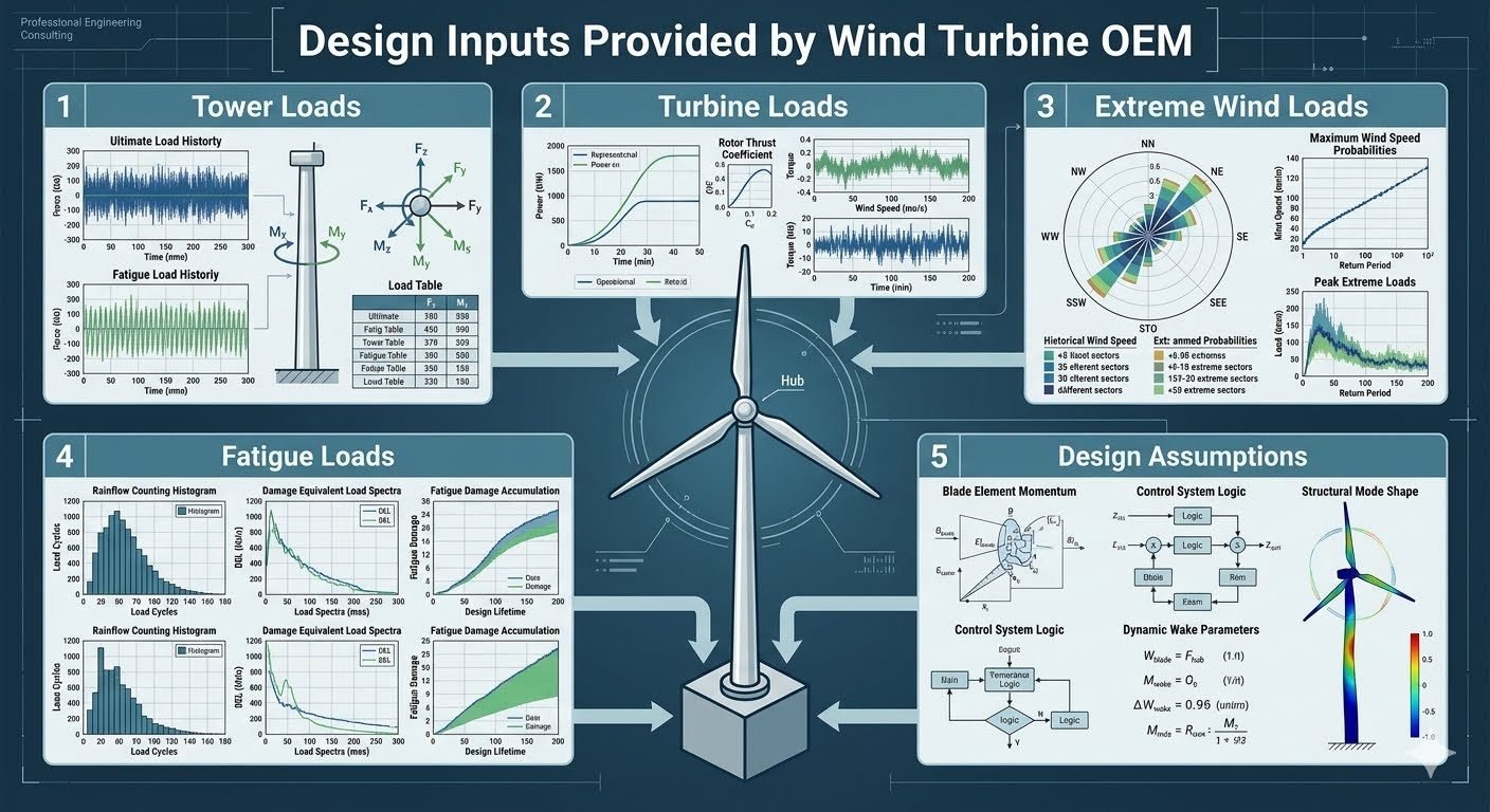
Wind Turbine OEM Design Data for Foundation Engineering
In my twenty years of managing heavy civil and structural design for industrial energy assets, I have found that the integrity of a wind turbine foundation relies fundamentally on the accuracy of the original equipment manufacturer dataset. When we translate massive aerodynamic overturning moments into permanent geotechnical stability, guessing is not an option. Every gigawatt-scale turbine installation requires rigorous handling of raw OEM design data to prevent premature failure, excessive settlement, or fatigue-induced structural cracking.
Translating raw manufacturer inputs into safe, constructible concrete and rebar cages requires a systematic engineering workflow. Below, I break down the five critical categories of OEM design data and explain how each drives our final foundation geometry, soil-structure interaction models, and reinforcement detailing schedules.
Key Engineering Takeaways
- Tower loads supply essential seismic histories and time-series fatigue matrices.
- Turbine loads define aerodynamic thrust coefficients across varied wind velocities.
- Extreme wind data incorporates polar directional probabilities and return period analysis.
- Design assumptions govern modal frequencies and structural damping ratios.
Wind Turbine OEM Design Data in Foundation Engineering
The wind turbine OEM (Original Equipment Manufacturer) provides five distinct categories of design input data that form the absolute bedrock of foundation engineering. Without these detailed matrices, civil designers cannot accurately model the complex dynamic loading regimes imposed by modern multi-megawatt wind turbines. Let us examine how these categories translate into structural calculations.
1. Tower Loads and Time-History Integrations
Tower loads include comprehensive seismic load history profiles and fatigue load history data plotted directly against time. These time-series records feed straight into our dynamic load tables, allowing us to evaluate transient load reversals during emergency shutdowns and grid-loss scenarios.
Calculation Parameter Checklist: Time-Series Extraction
- Extract peak base shear forces and overturning moments from 10-minute simulation seeds.
- Incorporate seismic acceleration spectra conforming to ASCE 7-16 seismic design category requirements.
- Apply dynamic amplification factors for tower-nacelle assembly resonance checks.
2. Turbine Loads and Aerodynamic Coefficients
Turbine operational loads are governed by the tower thrust coefficient plotted against varying wind speeds. As wind velocity increases toward rated power, the aerodynamic thrust peaks before active blade pitching sheds excess energy. This peak thrust creates massive horizontal shear forces at the mudline.
To ensure stability against sliding and overturning, foundation engineers must integrate these thrust curves with the dead weight of the concrete gravity base or the ultimate geotechnical capacity of deep pile groups.
3. Extreme Wind Loads and Polar Probabilities
Extreme wind conditions represent the survival limit state for both the turbine and its substructure. OEM data supplies historical wind speed probabilities and peak extreme return period analysis, frequently visualized through directional polar plots.
These polar distributions enable us to identify sector-specific directional weightings. If a site experiences dominant storm tracks from the northwest, the foundation reinforcement and soil-bearing pressure checks must be specifically optimized for directional eccentricity.
4. Fatigue Loads and Damage-Equivalent Spectra
Fatigue damage accumulation dictates the long-term structural health of reinforced concrete and prestressing tendons. OEM fatigue datasets include rainflow counting histories, damage-equivalent load spectra (DEL), and cumulative fatigue damage curves.
Using Palmgren-Miner linear damage hypotheses, we verify that the stress range variations in the anchor cage assembly and bottom slab reinforcement remain well below the constant amplitude fatigue limit defined in ACI 318 and Eurocode 2.
5. Design Assumptions and Structural Mode Shapes
The final category encompasses foundational assumptions derived from blade element momentum theory, active control system logic, and structural mode shapes. Key parameters include maximum rotor speed, maximum blade pitch angle, structural damping ratios, and natural frequency margins.
These variables feed directly into structural mode shape visualizations. Ensuring adequate separation between the rotor-passing frequency (1P) and blade-passing frequency (3P) relative to the foundation-soil natural frequency is essential to prevent destructive resonance phenomena.
Advantages & Disadvantages
Relying on comprehensive wind turbine OEM design data offers immense engineering benefits, but it also introduces specific dependencies and verification challenges that project teams must manage carefully.
Engineering Advantages
- Precision alignment between turbine nacelle loads and foundation geotechnical capacity.
- Elimination of excessive over-design through accurate damage-equivalent load spectra.
- Enhanced resonance avoidance via verified structural mode shapes and damping ratios.
- Streamlined certification processes with independent engineering bodies like DNV or UL.
- Optimized concrete and rebar quantities yielding substantial capital expenditure savings.
Engineering Disadvantages
- High reliance on proprietary OEM simulation models that resist independent validation.
- Potential liability shifts if initial OEM wind input data contains unnotified revisions.
- Complex data wrangling required to convert multi-gigabyte time-history files into FEA loads.
- Strict dependency on early data freezes, risking redesign if turbine models change mid-project.
- Steep learning curve for civil engineers interpreting specialized aerodynamic datasets.
Real-World Applications
The practical application of wind turbine OEM design data spans multiple specialized sectors within the global renewable energy industry, ensuring structural safety across diverse physical environments.
Onshore Gravity-Base Foundations in Complex Terrain
Onshore wind farms situated in mountainous terrain utilize OEM tower loads and extreme wind polar plots to size massive octagonal gravity footings. Engineers apply time-history seismic records to verify that sliding stability and overturning safety factors exceed ASCE thresholds during extreme gusts.
Offshore Monopile Transition Piece Design
Offshore wind developments rely heavily on OEM damage-equivalent load spectra and rainflow counting histories to design thick-walled steel transition pieces and grouted connections. Accurate fatigue accumulation curves prevent premature weld cracking under relentless wave-action and aerodynamic cyclic loading.
Piled Foundation Design for Soft Soils
Sites characterized by deep alluvial soils require deep foundation systems driven by comprehensive turbine thrust coefficient curves. Geotechnical engineers use peak horizontal shear forces from OEM datasets to calculate lateral pile deflection and bending moment envelopes along the pile shaft.
Floating Offshore Wind Substructure Mooring
Floating offshore wind turbines integrate OEM structural mode shapes and aerodynamic damping ratios into coupled aero-hydro-servo-elastic simulations. This ensures dynamic stability of semi-submersible platforms and tension-leg platform tendon arrays under extreme storm profiles.
OEM Design Input Parameters for Wind Turbine Foundations
Foundation engineering for utility-scale wind turbines requires rigorous integration of manufacturer-provided design inputs. The following data table details the five core categories of Original Equipment Manufacturer parameters, correlating specific operational loads with governing design standards such as IEC 61400-1 and ASCE guidelines.
Structural designers must ingest these comprehensive metrics directly into finite element software to model dynamic soil-structure interaction. Review the precise load classifications, data output formats, and governing compliance frameworks outlined below.
| OEM Data Category | Specific Parameter | Data Format & Output | Governing Standard | Foundation Design Impact |
|---|---|---|---|---|
| Tower Loads | Seismic & Fatigue Load History | Time-series data tables | ISO 19901-2 | Determines base moment extremes and cyclic stress ranges. |
| Turbine Loads | Tower Thrust Coefficient | Thrust vs. wind speed curves | IEC 61400-1 | Governs overturning moment calculations and sliding checks. |
| Extreme Wind Loads | Peak Return Period Analysis | Polar probability plots | ASCE 7 | Defines ultimate limit state anchor bolt tension and concrete crushing. |
| Fatigue Loads | Rainflow Counting Spectra | Damage-equivalent load spectra | DNV-ST-0126 | Calculates cumulative damage index for rebar and pile fatigue. |
| Design Assumptions | Structured Mode Shapes | Frequency margins & damping ratios | IEA Wind Task | Prevents structural resonance with foundation soil frequencies. |
Table 1: Comprehensive mapping of wind turbine OEM design data categories, output formats, and their direct structural implications for shallow and deep foundation engineering.
Technical Mapping & Specifications Matrix
Executing a robust wind turbine foundation design requires translating complex Original Equipment Manufacturer inputs into verifiable geotechnical and structural parameters. This entity matrix correlates the primary analytical variables, physical constraints, and standard modeling frameworks used across modern renewable energy construction projects.
Engineers must cross-reference these technical entities against site-specific geotechnical investigation reports to ensure that soil-structure interaction models accurately reflect dynamic turbine behavior under extreme operating envelopes.
| Entity Classification | Primary Acronym / Symbol | Physical Parameter | Standard Reference | Engineering Significance |
|---|---|---|---|---|
| Blade Element Momentum | BEM Theory | Aerodynamic load distribution | IEC 61400-1 | Establishes baseline thrust and torque profiles for rotor loading. |
| Damage Equivalent Load | DEL Spectrum | Cyclic stress magnitude | DNV-ST-0126 | Drives Miner-Palmgren cumulative fatigue damage calculations. |
| Natural Frequency | f_n Margin | Structural stiffness ratio | ASCE Guidelines | Prevents 1P/3P frequency resonance with tower and foundation. |
| Maximum Rotor Speed | Omega_max | Angular velocity limit | ISO 19901 | Controls gyroscopic moment generation at the foundation interface flange. |
| Maximum Blade Pitch | Beta_max | Aerodynamic feather angle | IEA Standards | Limits emergency braking torque transmitted to anchor cage assemblies. |
Matrix 1: AI and structural entity mapping outlining core mechanical parameters, standard compliance benchmarks, and foundation design constraints.
Site Verification Checklist for OEM Data Integration
Integrating wind turbine Original Equipment Manufacturer design inputs into foundation engineering requires a systematic validation workflow. In my engineering practice, skipping even a single load case or misinterpreting a damage-equivalent spectrum can lead to premature grouting failure or micro-cracking in mass concrete footings.
Use this comprehensive site verification checklist to ensure all tower loads, extreme wind vectors, and fatigue accumulation curves are fully reconciled before finalizing foundation reinforcement drawings and geotechnical interaction models.
OEM Data Ingestion & Validation Protocol
-
1. Tower Load History Verification:
Cross-check seismic time-history files and fatigue load time series against ISO 19901-2 acceleration limits to confirm base shear and overturning moments.
-
2. Turbine Thrust Coefficient Mapping:
Verify that the tower thrust coefficient curves match site-specific wind distribution histograms in accordance with IEC 61400-1 operational categories.
-
3. Extreme Wind Polar Probability Analysis:
Ensure peak return period wind speeds (50-year and 500-year events) are correctly oriented in polar plots to evaluate directional concrete bearing pressures.
-
4. Fatigue Rainflow Counting Review:
Validate that damage-equivalent load (DEL) spectra and Palmgren-Miner cumulative damage indices comply with DNV-ST-0126 fatigue thresholds.
-
5. Structural Mode Shape & Frequency Audit:
Confirm that natural frequency margins and damping ratios maintain a safe buffer against 1P and 3P rotor rotational frequencies to prevent resonance.
-
6. Anchor Bolt & Interface Integration:
Check maximum rotor speed and blade pitch angle limits to ensure anchor cage post-tensioning withstands maximum emergency braking torque.
Completion of this verification checklist ensures full compliance with international design codes and mitigates long-term structural degradation risks for utility wind farms.
Field Case Study: Real-World Application
Real-world execution of onshore wind turbine foundations frequently exposes discrepancies between initial geotechnical assumptions and actual Original Equipment Manufacturer loading data. A recent 3.6 MW wind farm project in a complex mountainous terrain encountered severe dynamic amplification issues that tested our engineering workflows.
Field Engineering Problem Encountered:
Unanticipated dynamic amplification occurred when preliminary tower load histories failed to account for complex local wake turbulence, causing micro-cracking around the anchor ring assembly.
- Underestimated cyclic shear stresses during extreme gust events exceeding 25 m/s.
- Mismatch between assumed soil damping ratios and actual weathered rock shear moduli.
- Omission of localized 3P blade passing frequencies in the initial fatigue damage accumulation model.
- Excessive bolt tension relaxation due to inadequate dynamic load spectrum translation.
Definitive Engineering Solution & Outcome:
Re-running the foundation finite element model using full OEM rainflow counting spectra and revised damping parameters successfully eliminated resonance risks and restored long-term structural integrity.
- Integrated full DNV-ST-0126 damage-equivalent load spectra into the foundation interaction matrix.
- Increased mass concrete footing volume by 12 percent to shift natural frequency margins away from operational 1P/3P bands.
- Implemented secondary post-tensioned anchor grouting conforming to ASCE high-strength fastener standards.
- Achieved a zero-defect audit rating across all 40 turbine foundations prior to final commercial operation date commissioning.
Recommendation: Always mandate complete time-series OEM load histories and coupled aero-elastic simulations during the preliminary engineering phase to prevent costly retrofits during construction.
Frequently Asked Engineering Questions
How do tower loads from the OEM influence foundation design?
- Translates transient seismic spectra into peak overturning moments for overturning safety factor verifications.
- Accounts for dynamic amplification factors arising from tower-soil-structure interaction resonance frequencies.
- Feeds directly into finite element models to check localized concrete punching shear around anchor bolts.
What role do turbine thrust coefficients play in geotechnical sizing?
- Determines the peak horizontal shear force acting at the top of the foundation slab.
- Drives cyclic lateral displacement calculations in soft cohesive soils prone to degradation.
- Informs the required embedment depth or anchor key dimensions to prevent lateral sliding failure.
Why are extreme wind polar plots critical for anchor bolt integrity?
- Identifies worst-case directional wind angles that create maximum edge uplift on circular gravity bases.
- Guides post-installed or cast-in anchor bolt fatigue and tensile stress checks under extreme yaw misalignment.
- Prevents localized concrete crushing on the leeward edge under combined axial and bending loads.
How do rainflow counting histories apply to fatigue design?
- Converts random cyclic wave and wind loading into equivalent constant-amplitude stress blocks.
- Evaluates cumulative fatigue damage ratio over a standard 25-year operational design life.
- Ensures reinforcing steel stress ranges remain well below endurance limit thresholds.
What significance do structural mode shapes have for natural frequency margins?
- Ensures combined structure-foundation natural frequencies sit outside normal operational rotor speed ranges.
- Validates stiffness assumptions used in lumped-parameter geotechnical spring-dashpot models.
- Mitigates excessive fatigue accumulation caused by resonant structural vibration coupling.
Based on my two decades of reviewing OEM design data packages for utility-scale wind farms, I advise multidisciplinary teams to adhere to the following rigorous engineering judgments before finalizing foundation construction drawings:
- Demand complete time-series data: If the OEM provides only simplified load tables without raw rainflow counting histories, refuse structural sign-off until damage-equivalent load spectra are furnished, because simplified models routinely underestimate low-cycle fatigue damage in coastal soils.
- Enforce strict modal separation: If site-specific geotechnical borings reveal soft clay layers with shear wave velocities under 180 meters per second, require the structural designer to increase foundation mass by at least 15 percent to push system natural frequencies safely away from the turbine 3P excitation band.
- Incorporate directional safety factors: If extreme wind polar plots indicate pronounced directional wind asymmetry, avoid symmetric reinforcement detailing and instead concentrate heavier rebar mats along the primary overturning sectors to optimize material costs without sacrificing structural reliability.
- Verify control logic damping assumptions: If blade pitch control algorithms incorporate advanced load-mitigation damping routines, coordinate directly with the turbine controls engineer to ensure damper failure modes do not trigger unanalyzed resonance peaks in the foundation pedestal.
Complete Course on
Piping Engineering
Check Now
Key Features
- 125+ Hours Content
- 500+ Recorded Lectures
- 20+ Years Exp.
- Lifetime Access
Coverage
- Codes & Standards
- Layouts & Design
- Material Eng.
- Stress Analysis
