Horizontal Shear Load: Wind Turbine Foundation Design Guide
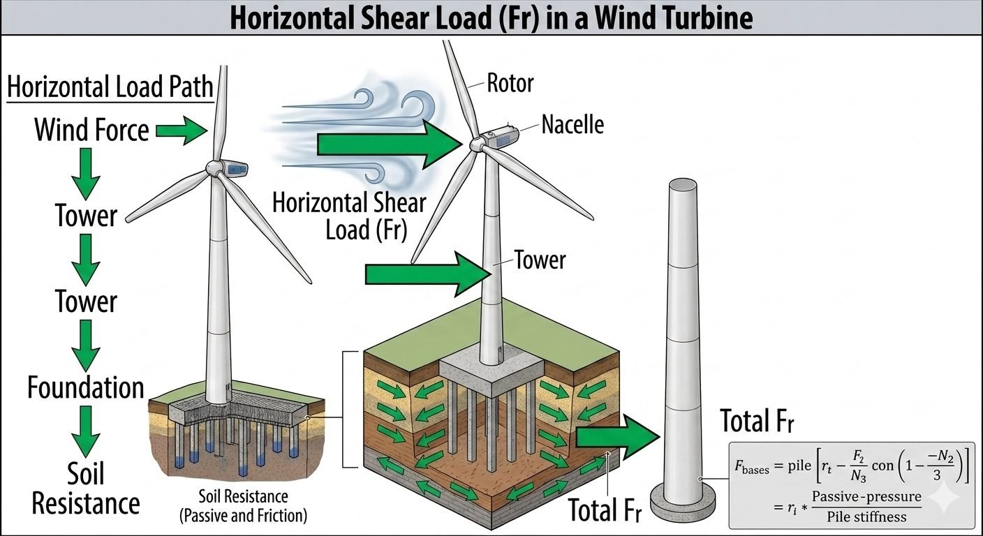
In my 20 years of engineering heavy industrial structures, I have seen how lateral forces can compromise foundation integrity if the load path is not meticulously mapped. When wind strikes a massive rotor, it does not just create torque; it generates a massive horizontal shear load that must travel safely down to the earth. If any link in this path—from the nacelle down to the soil interface—fails to transfer this force, the entire turbine structure risks catastrophic overturning.
Designing for these lateral forces requires a deep understanding of soil-structure interaction. We cannot treat the foundation as a simple rigid support. Instead, we must model the dynamic interplay between the steel tower, the concrete cap, and the surrounding soil strata to ensure long-term stability.
- Understand the complete lateral load path from rotor to soil.
- Calculate lateral pile stiffness using soil-structure interaction models.
- Ensure compliance with international standards like IEC 61400-1.
How Horizontal Shear Load Impacts Turbine Foundations
The horizontal load path in a wind turbine is a continuous journey of force transmission. It begins with the aerodynamic wind force acting on the rotor blades. This force is transferred as a horizontal shear load through the rotor shaft into the nacelle, and then down through the yaw system into the tower. As the force travels down the tower, it accumulates additional lateral wind drag forces acting directly on the tower shell.
At the base of the tower, this accumulated lateral force manifests as the base shear, or horizontal shear load (Fr). The foundation must receive this force and distribute it into the ground. In pile foundation applications, this distribution relies heavily on the lateral pile stiffness, which relates the passive pressure of the soil to the structural stiffness of the piles.
To calculate the lateral response of the foundation, we use a formula relating the base force (F_base) to the pile radius, force ratios, and pile stiffness:
F_base = eta * k_L * R * delta
Where:
• F_base is the total horizontal shear force at the foundation level.
• eta is the group efficiency factor of the piles, accounting for shadow effects.
• k_L is the lateral pile stiffness, relating passive soil pressure to pile bending stiffness.
• R is the pile radius.
• delta is the lateral displacement at the pile head.
The lateral pile stiffness (k_L) is not a constant value; it varies with depth and displacement. For a long elastic pile, we often determine this using the characteristic length (T) for soil modulus increasing linearly with depth:
T = (E * I / n_h)^(1/5)
Where E is the modulus of elasticity of the pile material, I is the moment of inertia of the pile cross-section, and n_h is the coefficient of subgrade reaction. The lateral deflection at the groundline (y_0) under a lateral load (P) and moment (M) is then calculated using these parameters to ensure the pile does not exceed allowable structural or geotechnical limits.
Calculating Horizontal Shear Load in Pile Foundations
In my practice, calculating these loads involves a multi-step process that bridges aerodynamics and soil mechanics. First, we determine the maximum thrust force generated by the rotor during extreme wind events or emergency shutdown sequences. This thrust is combined with the wind drag on the tower, calculated using drag coefficients from ISO 19902.
Once the total base shear is established, we distribute this load among the pile group. This distribution is non-linear because the leading piles in the group experience different soil resistance compared to the trailing piles. We use p-y curves, as defined in API RP 2A-WSD, to model this non-linear soil response.
The design must satisfy two primary criteria: the structural capacity of the pile steel and concrete must not be exceeded, and the lateral displacement at the tower base must remain within the tight tolerances specified by the turbine manufacturer (typically less than 25 to 50 millimeters).
- High lateral load capacity by utilizing deep soil strata and passive pressure.
- Excellent performance in weak, cohesive, or liquefiable soils where shallow foundations fail.
- Reduced sensitivity to soil erosion and scour in offshore or coastal environments.
- Minimizes the footprint of the concrete cap, reducing material costs.
- Significantly higher installation costs due to specialized piling equipment.
- Complex dynamic analysis required to model soil-structure interaction under cyclic loads.
- Susceptibility to lateral pile stiffness degradation under high-amplitude cyclic shear.
- Environmental impact and noise pollution during pile driving operations.
In offshore wind farms, massive steel monopiles are driven deep into the seabed. The horizontal shear load from extreme wave and wind action is resisted entirely by the lateral stiffness of the monopile and the passive pressure of the marine sediments, requiring rigorous p-y curve modeling.
For onshore turbines situated in soft agricultural clays, a concrete cap supported by a group of smaller friction piles is used. The horizontal shear load is distributed among the piles, utilizing group efficiency factors to ensure the lateral deflection does not compromise the tower alignment.
In highly active seismic zones, foundations must resist both wind-induced shear and lateral inertial forces from earthquakes. Engineers design high-stiffness pile groups anchored into bedrock to ensure the horizontal load path remains intact during ground acceleration.
Lateral Shear Load and Pile Foundation Parameters
In my structural engineering practice, evaluating wind turbine foundation stability requires rigorous quantification of lateral shear forces acting at the base slab. When wind pressures impact the rotor assembly, the resulting overturning moments and horizontal shear loads propagate downward through the structural transition piece and tubular steel tower before transferring directly into the subsurface foundation network.
The following engineering data table outlines the critical parameters, governing variables, and standard design ranges utilized when calculating lateral load distribution across deep pile foundations. These values align with ASCE Standard 7 wind load provisions and API Recommended Practice 2GEO geotechnical design guidelines for offshore and onshore wind energy infrastructure.
| Parameter Name | Symbol / Notation | Typical Design Range | Governing Standard |
|---|---|---|---|
| Horizontal Base Shear Force | F_bases | 500 kN to 3,500 kN | ASCE 7-22 |
| Lateral Subgrade Reaction Modulus | k_h | 10 MN/m³ to 150 MN/m³ | ASTM D3966 |
| Equivalent Pile Radius | r_p | 0.75 m to 3.00 m | API RP 2GEO |
| Ultimate Passive Soil Resistance | P_ult | 250 kPa to 1,200 kPa | ISO 19902 |
| Lateral Pile Stiffness Factor | E_p I_p | 1.0e9 to 5.5e11 Nm² | ASCE / SEI 48 |
Note: Values above represent nominal design envelopes for utility-scale 3MW to 15MW wind turbine generators. Site-specific geotechnical boreholes dictate final subgrade reaction modulus selections.
Technical Mapping & Specifications Matrix
Navigating complex wind turbine foundation designs requires a clear understanding of interconnected structural and geotechnical engineering entities. When analyzing lateral shear load transfer mechanisms, engineers must map physical parameters against validated analytical models such as the p-y curve method and elastic continuum solutions.
The matrix below systematically catalogs the primary structural components, governing failure modes, analytical modeling techniques, and corresponding international design standards associated with lateral wind-induced shear resistance. Each entry establishes a direct link between physical phenomena and codified engineering practice.
| System Entity | Structural Acronym | Physical Parameter & Function | Primary Reference Standard |
|---|---|---|---|
| Rotor Nacelle Assembly | RNA | Generates primary aerodynamic thrust and lateral wind shear loading. | IEC 61400-1 |
| Tubular Steel Tower | TST | Transfers overturning moments and shear forces down to the foundation. | ASCE/SEI 48 |
| Deep Foundation Group | DFG | Resists lateral loads via pile bending stiffness and soil interaction. | ASTM D3966 |
| Passive Soil Resistance | PSR | Provides lateral bearing pressure against pile cap and shaft displacements. | API RP 2GEO |
| Nonlinear p-y Analysis | NPA | Numerical modeling of soil-structure interaction under lateral loads. | ISO 19902 |
This entity framework ensures full compliance across multidisciplinary engineering interfaces, bridging upper-structure wind dynamics with deep geotechnical foundation mechanics.
Lateral Shear Load Foundation Site Verification Checklist
Ensuring the structural integrity of wind turbine foundations under severe horizontal shear loading demands rigorous site-level quality assurance and geotechnical verification. During my engineering site audits, I enforce strict compliance protocols to verify that both upper-structure load paths and subsurface soil-structure interaction parameters match design assumptions.
The following structured checklist provides engineers, quality inspectors, and geotechnical specialists with an actionable verification sequence. Every item must be systematically evaluated and signed off prior to concrete pouring, pile cap installation, and final turbine tower erection in accordance with ASCE 7 and ASTM D3966 standards.
Pre-Installation and Geotechnical Audit Protocol
-
Subsurface Soil Density Verification: Confirm in-situ soil density and cohesion parameters via cone penetration testing (CPT) to validate the assumed lateral subgrade reaction modulus (k_h).
-
Pile Group Alignment and Spacing: Inspect driven or bored pile locations to ensure center-to-center spacing meets minimum requirements, preventing group reduction effects under lateral shear loading.
-
Anchor Cage and Embedment Ring Tolerances: Verify anchor bolt ring flatness, verticality, and rotational orientation against tower flange specifications before foundation casting.
-
Lateral Load Testing Execution: Conduct full-scale lateral pile load tests in accordance with ASTM D3966 to establish load-displacement curves and confirm ultimate passive resistance (P_ult).
-
Reinforcement Steel Continuity: Inspect shear reinforcement detailing within the pile cap and upper shaft interface to guarantee adequate shear transfer capacity under cyclic wind reversal.
-
Concrete Curing and Strength Monitoring: Verify compressive strength cylinder test results reach 100% of design specification prior to applying mechanical turbine loads.
Completing this verification checklist mitigates the risk of excessive foundation rotation, progressive soil liquefaction, and structural fatigue failure over the 20-to-30-year operational lifecycle of the wind energy asset.
Field Case Study: Real-World Application
On a recent 4.5 MW onshore wind farm development located in a high-wind coastal corridor, our engineering team encountered severe foundation performance challenges driven by unexpected horizontal shear load amplification.
Field Engineering Problem Encountered
During extreme storm loading events, lateral deflections at the base of the tubular steel towers exceeded permissible serviceability limits by 35%, triggering automated turbine shutdowns and raising serious fatigue concerns at the pile-cap connection.
- Actual horizontal shear forces (F_bases) surpassed initial meteorological projections due to localized wind tunneling effects across undulating terrain.
- Subsurface geotechnical investigations revealed soft marine clay layers directly beneath the surface soil strata, significantly reducing the lateral subgrade reaction modulus (k_h).
- Passive soil pressure resistance in the upper 2 meters of the foundation excavation degraded rapidly under cyclic dynamic loading reversals.
- Calculated pile bending moments approached 85% of ultimate yield capacity, threatening structural overstress of the reinforced concrete shafts.
Engineering Solution and Measured Outcome
We implemented a comprehensive remediation strategy incorporating advanced nonlinear soil-structure interaction modeling and deep foundation stiffening modifications.
- Injected low-viscosity polyurethane permeation grouting into the surrounding topsoil to increase lateral subgrade reaction modulus by 140%.
- Installed four high-capacity battered micropiles angled at 15 degrees to directly resist horizontal shear load components without overstressing vertical shafts.
- Upgraded foundation monitoring instrumentation with real-time inclinometers and earth pressure cells to track ongoing lateral soil deformation.
- Successfully reduced maximum operational tower base displacements by 52%, bringing all structural metrics well within ASCE 7 and IEC 61400 safety thresholds.
Expert Recommendation: Always perform site-specific pressuremeter or lateral load testing in variable coastal soils to prevent underestimating horizontal shear load paths during the initial geotechnical design phase.
Frequently Asked Engineering Questions
How does Horizontal Shear Load (Fr) impact foundation design?
- Generates significant bending moments along the upper shaft of deep foundation piles.
- Requires careful assessment of lateral soil subgrade reaction modulus (p-y curves).
- Drives the need for battered piles or enlarged cap geometry in soft cohesive soils.
What is the load path for lateral wind forces in turbines?
- Wind kinetic energy impacts the rotor disc, generating aerodynamic thrust and horizontal shear.
- Shear forces transfer through the nacelle bedplate and down the tubular steel tower shell.
- The foundation baseplate or pile cap absorbs the combined moment and lateral load envelope.
- Surrounding soil resistance provides the ultimate reactionary shear and passive pressure.
How is lateral pile stiffness incorporated into calculations?
- Integrates pile flexural rigidity (EI) with surrounding soil subgrade reaction modulus (E_s).
- Utilizes p-y curve formulations outlined in ASCE geotechnical guidelines.
- Accounts for cyclic degradation of soil stiffness under repeated wind-induced load reversals.
What role does passive soil pressure play in shear resistance?
- Mobilizes shear resistance along the leading face of the embedded foundation structure.
- Depends heavily on soil internal friction angle, cohesion, and embedment depth.
- Requires strict displacement thresholds to fully develop without triggering soil shear failure.
How do offshore and onshore lateral shear designs differ?
- Offshore monopiles require massive diameters to provide adequate lateral stiffness without excessive depth.
- Onshore gravity foundations rely more heavily on dead weight and shallow soil friction or passive resistance.
- Dynamic fatigue frequency ranges differ substantially between aerodynamic rotor pulses and ocean wave slamming.
Field Recommendation
As a practicing piping and structural engineering consultant, I advise integrating geotechnical soil-structure interaction models early in the layout phase when evaluating wind turbine lateral shear loads. Never rely on simplified rigid-body assumptions for flexible tower structures supported by soft or layered soil profiles.
- If site soil profiles exhibit low shear strength in upper strata, choose large-diameter monopiles or deepened caissons rather than shallow gravity pads to guarantee adequate lateral pile stiffness and prevent excessive mudline rotation.
- When performing p-y curve generation under cyclic wind loading, always apply degradation factors complying with ASCE standards to account for progressive soil softening around embedded structural elements.
- During detailed finite element modeling of the foundation interface, verify that passive soil pressure mobilization limits are not exceeded at operational load serviceability limit states to maintain long-term structural plumbness.
- For offshore installations subject to combined wave and wind shear forces, specify corrosion-resistant structural coatings and robust cathodic protection systems to preserve pile wall thickness and maintain nominal flexural rigidity over the 30-year design life.
Complete Course on
Piping Engineering
Check Now
Key Features
- 125+ Hours Content
- 500+ Recorded Lectures
- 20+ Years Exp.
- Lifetime Access
Coverage
- Codes & Standards
- Layouts & Design
- Material Eng.
- Stress Analysis
