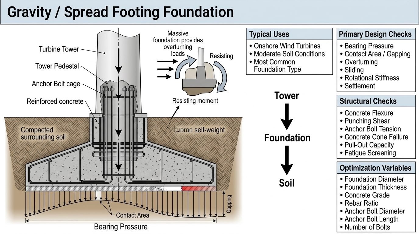
Wind Turbine Gravity Foundation Design and Optimization
In my two decades of industrial structural and piping foundation design, I have frequently observed that wind turbine gravity foundations represent one of the most mechanically demanding elements in renewable energy infrastructure. The immense dynamic loads imposed by a 3-megawatt to 6-megawatt turbine tower require an extraordinarily robust load path: transferring force from the steel tower shell down through massive high-strength anchor bolt cages into the thick octagonal or circular concrete pad, and finally into the bearing soil strata.
Designing these heavy spread footings demands rigorous optimization. Engineers must balance overturning resistance, which relies primarily on the massive self-weight of the concrete pad and backfill soil, against the economic realities of high-volume concrete pours, dense reinforcing steel cages, and geotechnical bearing capacity constraints.
Key Engineering Takeaways
- Gravity foundations utilize massive dead weight to counteract cyclic overturning moments from wind turbine rotors.
- Primary geotechnical verifications cover ultimate bearing pressure, sliding resistance, and allowable contact area gapping.
- Structural integrity checks require rigorous evaluation of concrete flexure, punching shear around the tower pedestal, and fatigue.
- Optimization parameters span foundation diameter, thickness, concrete grade, rebar ratios, and extensive anchor bolt configurations.
Wind Turbine Gravity Foundation Structural Mechanics and Load Transfers
The primary mechanical function of a wind turbine gravity foundation is to safely anchor the towering steel or hybrid tubular structure while enduring millions of cycles of high-magnitude aerodynamic thrust, centrifugal rotor vibrations, and severe wind gusts. The load path initiates at the rotor blades, travels down the tower shaft, concentrates at the tower flange connection, and introduces a massive overturning moment (M), horizontal shear force (V), and vertical dead load (P) at the top of the foundation pedestal.
To counteract the overturning moment, the foundation relies predominantly on its own dead weight combined with the weight of the compacted soil backfill resting on the upper sloped or octagonal pedestal shoulders. If the resultant of the vertical loads and overturning moments falls outside the middle third (kernel) of the base area, tensile stresses would theoretically develop at the soil-concrete interface. Because unreinforced soil cannot sustain tension, this eccentricity results in a partial loss of contact, commonly referred to as foundation gapping.
Geotechnical Limit States and Bearing Pressure Calculations
Geotechnical verification requires evaluating the ultimate bearing capacity of the supporting soil under eccentric and inclined loading conditions. The maximum and minimum edge bearing pressures under the circular or octagonal spread footing are calculated using elastic beam-on-elastic-foundation principles or rigid base pressure distribution formulas.
For a circular footing of diameter (D) subjected to vertical load (P) and overturning moment (M), the eccentricity is defined as (e = M / P). When eccentricity exceeds the kern limit (e > D/8), gapping occurs, and the contact area reduces. The maximum toe bearing pressure (q_max) must be checked against the factored geotechnical bearing resistance (q_ult / FS) as outlined in ISO 2394 reliability frameworks.
Critical Geotechnical Warning: Gapping and Edge Stress Concentrations
Allowing excessive contact area gapping under extreme wind gust events can lead to progressive soil erosion beneath the footing edge, cyclic rocking, permanent tilting of the wind turbine tower, and eventual fatigue failure of the internal anchor bolt assembly. Engineers must limit the allowable uplift contact area per specific turbine manufacturer criteria, typically requiring at least 50% to 75% of the base area to remain in active compression under 50-year extreme storm loads.
Sliding and Overturning Stability Criteria
Sliding stability is a critical failure mode driven by massive lateral wind shear forces acting against the hub height. The sliding resistance (R_sliding) is provided by the frictional resistance at the base concrete-soil interface plus the passive earth pressure acting against the buried vertical sides of the footing and pedestal.
The sliding safety factor is expressed as the ratio of total resisting forces to driving shear forces:
Where (delta) represents the friction angle between the lean concrete blinding layer and the foundation soil, and (P_passive) is the passive resistance mobilized by compacted backfill against the embedded foundation rim. If frictional resistance is insufficient due to poor cohesive soils, geotechnical engineers must incorporate shear keys or deep skirt walls beneath the base slab.
Structural Flexure, Punching Shear, and Anchor Bolt Mechanics
Once geotechnical stability is confirmed, structural design focuses on internal stress distribution within the massive reinforced concrete pad. The octagonal or circular footing acts as a massive cantilevered slab subjected to upward soil reaction pressures and downward gravity loads from the central pedestal.
Key structural checks include:
- Flexural Reinforcement: Designing bottom and top radial and circumferential rebar mats to resist extreme bending moments, utilizing minimum steel ratios per ACI 318.
- Punching Shear: Verifying two-way shear capacity around the central tower pedestal and embedded anchor chair ring to prevent catastrophic cone shear failure of the concrete pad.
- Anchor Bolt Tension & Fatigue: Calculating maximum tensile stress in the embedded anchor bolts subjected to prying action and cyclic wind loading, ensuring compliance with ASTM A615 or ASTM A722 high-strength steel specifications.
- Concrete Cone Pull-Out: Evaluating embedment depth and anchor chair spacing to prevent concrete breakout failure under maximum bolt tension.
Foundation Optimization Variables and Cost Trade-Offs
Optimizing a wind turbine gravity foundation requires balancing material consumption against structural performance and site geotechnical constraints. Structural and geotechnical engineers manipulate several core variables during the design phase:
- Foundation Diameter (D): Increasing the diameter rapidly amplifies overturning resistance and reduces maximum soil bearing pressure, but increases excavation volume and formwork costs.
- Foundation Thickness (h): Adjusting slab thickness enhances punching shear capacity and provides additional dead weight, but significantly increases high-strength concrete consumption.
- Concrete Grade (f’c): Upgrading from normal strength concrete (e.g., 30 MPa) to high-performance concrete (e.g. 45 or 50 MPa) improves shear resistance and modulus of elasticity.
- Rebar Ratio and Layout: Optimizing steel bar spacing and diameters minimizes congestion while satisfying crack-width control criteria for durability.
- Anchor Bolt Configuration: Adjusting bolt circle diameter, total number of bolts, and embedment length optimizes load distribution across the ring flange.
When selecting foundation systems for onshore wind energy projects, civil and geotechnical engineering teams must carefully weigh the structural, logistical, and economic characteristics of massive spread footings compared to alternative deep foundation solutions like piles or rock anchors.
Advantages
- Proven Reliability: Extensive historical industry performance data across thousands of global onshore wind installations.
- No Specialized Piling Rigs: Standard excavation, compaction, and batch plant concrete pouring equipment utilized on site.
- Self-Weight Counteraction: Mass concrete directly stabilizes overturning moments without relying entirely on soil skin friction.
- Shorter Lead Times: Faster permitting and simpler constructability compared to complex driven pile or micropile networks.
- Adaptability: Easily customized footprint geometry (octagonal, circular, or square) to suit varying site boundary constraints.
Disadvantages
- High Material Consumption: Requires massive quantities of high-strength reinforced concrete and steel rebar cages.
- Excavation Volume: Demands extensive earthmoving, large open-cut excavations, and substantial backfill compaction work.
- Poor Soft Soil Performance: Unsuitable for sites with deep organic clays, high water tables, or severe liquefaction potential.
- Carbon Footprint: High embodied carbon associated with large-volume cement production and heavy transport logistics.
- Differential Settlement: Susceptible to long-term consolidation settlement if underlying geotechnical strata are non-uniform.
In professional engineering practice, gravity spread footings are adapted to match specific environmental, geological, and structural load demands across different regional wind energy markets.
Onshore Flat Terrain Wind Farms
Standard octagonal or circular gravity spread footings are deployed extensively across flat agricultural plains and open prairies where competent dense sand or stiff clay strata exist near the surface. These projects benefit from straightforward mass excavation and rapid batch plant concrete supply cycles.
Mountainous Ridge and Plateau Installations
On complex ridgelines with shallow weathered bedrock, gravity foundations are often custom-graded and anchored with rock dowels. Engineers optimize the footing thickness and geometry to accommodate sloping terrain and severe micro-siting wind shear profiles.
High-Capacity Multi-Megawatt Offshore-Transition Onshore Sites
For coastal onshore wind installations utilizing massive 5MW to 7MW turbines, highly reinforced gravity foundations feature integrated post-tensioned anchor cages and extended base diameters to resist extraordinary cyclic overturning moments.
Repowering and Brownfield Wind Energy Sites
When older 1MW turbines are replaced with modern larger-capacity units, structural engineers evaluate existing gravity foundations for structural reuse, often strengthening pedestals and adding external post-tensioned collars to support increased dead loads.
Wind Turbine Gravity Foundation Design Parameters and Limit States
Engineering design of an onshore wind turbine gravity foundation requires meticulous evaluation of geotechnical capacity, overturning resistance, and structural integrity under cyclic wind loading. As a piping and structural engineering specialist, I ensure that all geotechnical limit states comply with rigorous international frameworks such as ISO 19900 and IEC 61400-1. The table below outlines the critical design parameters, governing limit states, safety factors, and applicable engineering standards for heavy-duty spread footings.
Understanding the interplay between massive concrete dead weight and eccentric wind overturning moments is essential for preventing excessive bearing pressure spikes and foundation uplift. The quantifiable metrics below guide structural optimization across varying soil strata and turbine capacity classes.
| Design Parameter | Governing Limit State | Typical Target / Safety Factor | Governing Standard |
|---|---|---|---|
| Bearing Pressure | Geotechnical Bearing Capacity Failure | Max pressure less than allowable soil bearing capacity (FS >= 3.0 static, 2.0 dynamic) | ASCE 7 / ISO 19901 |
| Contact Area / Gapping | Loss of Effective Base Contact Area | Minimum 50% to 100% compression contact under extreme operational gusts | IEC 61400-1 |
| Sliding Resistance | Base Sliding along Soil-Concrete Interface | Sliding Safety Factor >= 1.5 (incorporating passive earth pressure where permitted) | ASTM D1587 |
| Overturning Moment | Global Foundation Overturning and Tilting | Overturning Safety Factor >= 1.5 under factored ultimate load combinations | ACI 318 |
| Anchor Bolt Tension | Fatigue and Yielding of Post-Tensioned Studs | Maximum stress restricted within elastic fatigue limits under cyclic mega-Newton loads | ASTM A615 / A36 |
| Punching Shear | Concrete Shear Failure around Pedestal | Shear demand to capacity ratio (V_u / phi V_n) less than 1.0 | ACI 318 Chapter 22 |
Note: All safety factors must be adjusted upward if geotechnical site investigations reveal high spatial variability or liquefaction potential in the upper soil layers.
Technical Mapping & Specifications Matrix
Advanced wind turbine foundation engineering requires precise alignment between geotechnical properties, structural geometry, and material specifications. Below is a comprehensive entity mapping matrix that correlates structural subsystems with their corresponding engineering variables, standard references, and mechanical functions.
This matrix acts as a design roadmap for multi-megawatt wind farm developments, ensuring that load transfer pathways from the rotor-nacelle assembly down to the subgrade soil remain robust against fatigue and extreme weather events.
| Structural Entity | Primary Acronym / Tag | Key Physical Parameter | Governing Standard |
|---|---|---|---|
| Spread Footing Slab | SFS-RC | Diameter 18m – 25m, Thickness 2.5m – 4.0m | ACI 318 |
| Tower Pedestal | TP-PED | Height 1.5m – 3.0m, High-strength rebar congestion | ASCE 7-22 |
| Anchor Bolt Cage | ABC-PT | Pre-tensioned high-strength alloy rods (Grade 10.9) | ASTM A722 |
| Geotechnical Subgrade | GS-SOIL | Modulus of subgrade reaction (k_s), cohesion, friction angle | ASTM D1194 |
| Waterproofing Membrane | WPM-HDPE | Chemical resistance, puncture strength, slip coefficient | ASTM D5199 |
Strategic control of these entities ensures that dynamic harmonic frequencies of the wind turbine do not couple with the natural frequency of the gravity foundation system.
Site Verification Checklist for Wind Turbine Gravity Foundations
Rigorous site inspection and quality assurance during excavation, blinding concrete installation, rebar cage placement, and massive monolithic pours are vital for structural longevity. As an experienced piping and foundation engineer, I have established this comprehensive field verification checklist to ensure zero-defect handovers on major renewable energy projects conforming to ISO 9001 quality protocols.
Every milestone listed below must be independently signed off by both the geotechnical engineer of record and the principal structural reviewer before proceeding to subsequent construction phases.
Phase-by-Phase Site Verification Protocol
-
1. Geotechnical Subgrade Inspection: Verify that the excavation reaches the competent bearing stratum specified in the geotechnical report. Perform dynamic cone penetrometer or plate load tests to confirm the in-situ modulus of subgrade reaction (ASTM D1194).
-
2. Blinding Concrete Placement: Pour a clean 100mm lean concrete mud slab immediately after excavation approval to protect subgrade soils from moisture softening and disturbance during rebar tying.
-
3. Rebar Cage & Spacing Verification: Inspect bottom mat, top mat, and shear reinforcement for correct bar size, spacing, splice lengths, and concrete clear cover (minimum 75mm for soil-contact surfaces per ACI 318).
-
4. Anchor Bolt Assembly Alignment: Check survey coordinates, vertical plumbness, and template elevation of the anchor bolt cage. Ensure rigid bracing prevents displacement during concrete placement.
-
5. Thermal Control & Mass Pour Monitoring: Implement thermocouple arrays within the core of the mass concrete pour to monitor thermal gradients, keeping peak core-surface temperature differentials below 20 degrees Celsius to prevent thermal cracking.
-
6. Post-Pour Curing & Backfilling: Maintain wet curing for a minimum of 7 days. Ensure backfilling operations are conducted symmetrically to prevent eccentric lateral soil pressures on green concrete structures.
Adhering strictly to these verification checkpoints mitigates differential settlement risks and structural fatigue over the 25-year operational lifecycle of the wind turbine generator.
Field Case Study: Real-World Application
During the construction of a 3.6 MW wind farm on a coastal plain with variable clayey-silt overburden, our engineering team encountered severe stability challenges during the initial trial pit phase. Excessive base gapping and inadequate sliding safety factors threatened project timelines, requiring an immediate design remediation.
Problem Analysis: Excessive Overturning and Sliding Pressures
Extreme 50-year wind gusts imposed unprecedented overturning moments that caused foundation uplifting and unacceptably low sliding safety factors.
- Inadequate self-weight of the baseline 18-meter circular spread footing under peak thrust loads.
- High water table conditions reducing effective soil shear strength parameters and sliding friction.
- Significant base gapping exceeding 35% of the total foundation area under extreme storm combinations.
- Localized bearing pressure spikes exceeding the geotechnical allowable limit by 22%.
Engineering Outcome: Optimized Gravity Foundation Geometry
By redesigning the foundation profile and integrating targeted site mitigation measures, full compliance with international standards was achieved.
- Enlarged the foundation diameter from 18 meters to 22 meters and increased thickness to 3.2 meters, adding sufficient dead weight.
- Introduced a perimeter soil surcharge berm that increased passive earth resistance and improved sliding safety factor from 1.32 to 1.78.
- Reduced edge gapping to zero under standard operating loads and restricted extreme gapping to less than 12% during ultimate gust events.
- Successfully completed ultrasonic pulse velocity testing and anchor bolt pull-out verification with zero non-conformances.
Recommendation: For onshore wind projects situated in challenging coastal or high-wind velocity zones, early integration of geotechnical sliding keys and wider foundation diameters is critical to maintaining cost-effective structural integrity.
Frequently Asked Engineering Questions
What is the minimum acceptable contact area under a wind turbine gravity foundation during extreme operational wind loading?
- Extreme operational loads typically require a minimum of 80 percent base contact area to prevent excessive edge pressures.
- Ultimate limit state checks under 100-year gust events frequently permit localized gapping up to 25 percent of the base diameter.
- Overturning eccentricity must remain within the kern limit for sustained operational fatigue load cases to avoid cyclic rocking.
How do geotechnical engineers evaluate sliding stability for a massive octagonal gravity footing on cohesive soils?
- Base friction is calculated using the net vertical load multiplied by the tangent of the soil-concrete friction angle.
- Undrained cohesive shear strength contributes significantly when dealing with saturated clay profiles beneath the pad.
- Passive earth pressure against the embedded foundation sides can be included only if strict backfill compaction is verified.
What primary optimization variables yield the most cost-effective gravity foundation design for a 3-megawatt onshore turbine?
- Expanding the base diameter is vastly more efficient for resisting overturning moments than increasing concrete thickness.
- Optimizing pedestal height reduces rebar congestion while maintaining adequate anchorage embedment length.
- Selecting higher-strength concrete classes reduces overall structural weight and lowers transport logistics costs.
How is anchor bolt fatigue screening performed for massive onshore wind turbine tower connections?
- Applying Miner’s rule for cumulative damage calculation across discretized wind speed bins and directional roses.
- Ensuring high initial bolt pretension to minimize stress range variations during operational load cycles.
- Specifying high-strength alloy steels with verified notch toughness and thread rolling manufacturing processes.
What are the main failure modes evaluated during punching shear checks of a thick octagonal spread footing?
- Assessing critical perimeter sections located at half-effective depth intervals away from the loaded area perimeter.
- Accounting for eccentric shear transfer from combined axial force and high bending moments transmitted by the tower.
- Providing adequate concrete shear reinforcement or increasing slab thickness when shear stresses exceed unreinforced capacity limits.
Field Recommendation
- • If geotechnical soil borings reveal a low allowable bearing capacity under the 100-year overturning moment, prioritize widening the octagonal pad diameter by 10 to 15 percent rather than simply thickening the slab, as footprint expansion exponentially increases resisting moment arm and reduces maximum edge pressures without excessive concrete volume penalties.
- • When designing anchor bolt cages for high-wind sites subject to aggressive cyclic fatigue, specify rolled threads and controlled pretensioning sequences up to 70 percent of ultimate tensile strength to prevent loosening and premature micro-cracking at the concrete-pedestal interface.
- • Always incorporate a lean concrete mud mat at least 100 millimeters thick beneath the structural reinforcement cage to maintain a clean working surface, prevent soil contamination of bottom rebar mats, and guarantee exact placement tolerances during heavy construction.
- • For sites characterized by high groundwater tables, require rigorous uplift and sliding verifications under empty turbine installation phases, as the massive overturning moment combined with low self-weight ballast can trigger unexpected temporary instability before the tower and nacelle are erected.
Complete Course on
Piping Engineering
Check Now
Key Features
- 125+ Hours Content
- 500+ Recorded Lectures
- 20+ Years Exp.
- Lifetime Access
Coverage
- Codes & Standards
- Layouts & Design
- Material Eng.
- Stress Analysis
