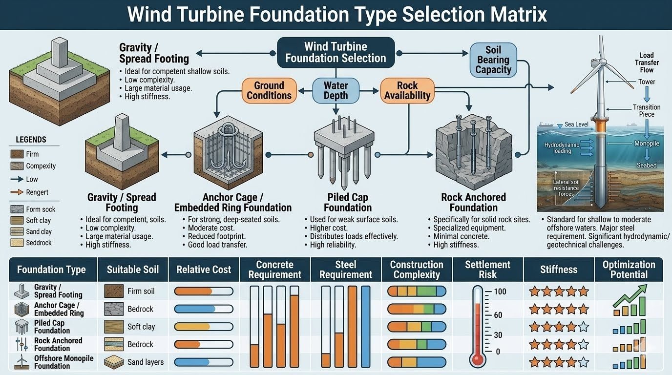
Wind Turbine Foundation Selection Matrix: Expert Engineering Guide
In my two decades of heavy industrial and structural design experience, selecting the correct wind turbine foundation is the single most critical factor governing long-term asset integrity. Wind turbine generators impose massive dynamic overturning moments, eccentric cyclic thrust loads, and high-frequency vibrations that test the absolute limits of geotechnical engineering. When designing onshore or offshore wind farms, ignoring site-specific ground conditions inevitably leads to excessive settlement, dynamic coupling failures, or catastrophic fatigue damage.
Engineers cannot rely on rule-of-thumb heuristics for modern 15MW+ wind turbines. We must deploy a rigorous wind turbine foundation selection matrix that quantitatively evaluates soil bearing capacity, groundwater tables, rock head proximity, and hydrodynamic loading. Throughout this guide, I break down the five primary foundation typologies, evaluate their structural mechanics, and provide actionable design methodologies aligned with international standards.
Engineering Key Takeaways
- Ground conditions dictate the feasibility window across gravity, piled, and anchored foundation types.
- Dynamic amplification factors require careful verification against soil-structure interaction resonance.
- Overturning moments govern eccentric base sizing under extreme survival wind speed combinations.
- Compliance with IEC 61400-1 is mandatory for all ultimate and fatigue limit state verification.
Wind Turbine Foundation Selection Matrix and Design Mechanics
The process of selecting a wind turbine foundation starts with a comprehensive geotechnical site investigation. We evaluate cone penetration testing (CPT) data, standard penetration test (SPT) N-values, and undrained shear strength parameters. The core objective of the wind turbine foundation selection matrix is to channel these raw soil metrics into an optimized structural archetype that minimizes differential settlement while safely transferring immense cyclic moments into the earth.
Let us examine the mechanical behavior of the five primary structural variants governed by the selection matrix. Each archetype addresses specific geotechnical constraints, balancing material expenditure against constructability limits and long-term fatigue performance under continuous wind loading.
1. Gravity and Spread Footing Foundation Mechanics
Gravity spread footings rely on massive dead weight to counteract the overturning moments generated by aerodynamic rotor thrust. Typically constructed as large octagonal or circular reinforced concrete slabs, these foundations require competent shallow soils with high bearing capacity to prevent bearing failure.
From a structural design perspective, the base must be proportioned such that the resultant load vector under extreme 50-year gust conditions remains within the middle third (kern) of the base area. This eliminates tensile stress zones beneath the concrete interface, preventing progressive gap formation and rocking fatigue.
Geotechnical Warning: Edge Bearing Failure and Uplift
In shallow spread footing designs under severe wind gusts, eccentric loading can cause high toe pressures that exceed the allowable bearing capacity of the soil. If uplift occurs across more than twenty percent of the base area, stress concentrations on the remaining contact patch accelerate local soil yielding and tilting.
Designers must verify safety factors against sliding and overturning in accordance with ISO 19901-4, ensuring adequate ballast mass and friction coefficients at the base-soil interface.
2. Anchor Cage and Embedded Ring Foundation Systems
Embedded ring foundations utilize a rigid steel anchorage assembly deeply embedded within a conical or cylindrical concrete block. This typology is specifically tailored for strong, deep-seated soils where structural depth can be leveraged to distribute high moment loads more efficiently than a flat spread footing.
The load transfer mechanism relies on composite action between the embedded steel ring, high-strength post-tensioned anchor bolts, and the surrounding mass concrete. This minimizes the physical footprint at the surface while maintaining exceptional rotational stiffness required to limit tower top deflection.
3. Piled Cap Foundation Architecture
When surface soils exhibit low shear strength, high compressibility, or thick alluvial deposits, spread footings become structurally unviable due to excessive immediate and long-term consolidation settlement. In these conditions, the selection matrix routes the design toward a piled cap foundation.
A thick reinforced concrete pile cap ties a cluster of driven steel H-piles, steel pipe piles, or bored cast-in-place concrete friction/end-bearing piles together. The piles transfer the massive axial and lateral loads down through weak superficial strata into competent deep bedrock or dense bearing strata.
4. Rock Anchored Foundation Design
At sites where competent rock lies at or very near the ground surface, massive gravity blocks are economically and logistically impractical due to excessive excavation and concrete volumes. The rock anchored foundation provides an elegant, high-stiffness alternative.
This system utilizes high-strength steel tendons or rock anchors drilled deep into the sound bedrock and tensioned against a relatively thin concrete distribution cap. The anchors pre-stress the rock mass, effectively creating an artificial gravity anchor that resists large overturning moments with minimal concrete usage.
5. Offshore Monopile Foundation Engineering
For offshore wind farms in shallow to moderate water depths (typically up to 40 meters), the large-diameter steel monopile remains the industry benchmark. Driven or drilled into the seabed, the monopile acts as a massive cantilever beam resisting combined wave, current, and aerodynamic turbine thrust loads.
Geotechnical design of monopiles relies heavily on p-y curve analyses defined in API RP 2GEO and DNV-ST-0126 to model lateral soil-structure interaction. Fatigue damage accumulation from cyclic wave action and blade rotation frequency must be rigorously evaluated across the entire operational lifespan.
Every foundation archetype carries distinct engineering compromises. Weighing structural efficiency against geotechnical constraints and supply chain realities ensures optimal project delivery.
Engineering Advantages
- Gravity footings eliminate complex subsurface piling operations, reducing specialized equipment mobilization costs.
- Rock anchored systems minimize excavation volume and concrete consumption on mountainous or rocky terrain.
- Piled cap foundations provide superior settlement control in soft, compressible alluvial soils.
- Embedded ring configurations offer high rotational stiffness, limiting wind turbine tower top deflection.
- Offshore monopiles allow rapid installation cycles using standard heavy-lift floating crane vessels.
Engineering Disadvantages
- Spread footings require massive material quantities, resulting in heavy carbon footprints and transport logistics burdens.
- Rock anchors demand rigorous corrosion protection systems and specialized post-tensioning quality control.
- Piled cap foundations introduce high financial risk if subsurface obstructions or driving refusals occur.
- Offshore monopiles face severe fatigue loading from hydrodynamic wave-current interactions and vortex shedding.
- Deep embedded ring structures require complex temporary shoring and deep excavation dewatering operations.
Applying the foundational matrix in active industrial projects requires aligning site geology with turbine capacity. The following deployment profiles illustrate real-world engineering selections.
Onshore Inland Plain Wind Farms
Flat agricultural plains with deep, competent clay deposits typically favor large reinforced concrete gravity spread footings. The absence of shallow rock and the presence of stable cohesive soils allow civil contractors to excavate, pour, and backfill rapidly without specialized piling rigs.
Mountainous Ridge Developments
Ridgeline wind installations frequently encounter shallow, weathered bedrock interspersed with steep topography. Here, rock anchored foundations excel by anchoring the turbine directly into sound parent rock, eliminating the need for massive excavation benches and reducing environmental disturbance.
Coastal Delta and Marshland Sites
Coastal wetlands and river deltas present severe geotechnical challenges due to deep, soft, saturated silt and clay layers prone to liquefaction and excessive settlement. Piled cap foundations become mandatory in these environments to bypass weak strata and anchor structural loads into deep bearing layers.
Shallow Water Offshore Installations
Offshore wind farms in transitional waters up to 40 meters deep rely almost exclusively on massive steel monopiles driven into sandy or clayey seabeds. These structures withstand harsh marine environments while transferring cyclic wave and rotor thrust loads efficiently.
High-Capacity Repowering Projects
When replacing legacy 2MW turbines with modern 6MW+ units on existing wind farms, embedded ring foundations with retrofitted post-tensioned anchors are often deployed. This allows higher capacity loading without requiring complete demolition of the original foundation footprint.
Wind Turbine Foundation Selection Matrix and Technical Comparison
Selecting the appropriate structural support for utility-scale wind generation requires a rigorous multidisciplinary evaluation of geotechnical mechanics, material logistics, and long-term dynamic loading characteristics. In my structural design practice, I utilize this comprehensive matrix to align site-specific soil mechanics with the structural performance profiles defined in ISO 19900 and DNV-ST-0126 guidelines.
The following comparative matrix synthesizes the five primary wind turbine foundation typologies across critical geotechnical criteria, commercial factors, and material volumes. Each system behaves uniquely under the combined overturning moments and axial thrust generated by modern multi-megawatt wind turbines.
| Foundation Type | Suitable Soil / Ground | Relative Cost | Concrete Req. | Steel Req. | Complexity | Settlement Risk | Stiffness Rating | Optimization Potential |
|---|---|---|---|---|---|---|---|---|
| Gravity / Spread Footing | Competent shallow soils, dense sand/gravel | Low to Moderate | Very High | Moderate | Low | Low (if properly compacted) | 4 / 5 Stars | Medium (Ballast optimization) |
| Anchor Cage / Embedded Ring | Strong, deep-seated cohesive soils | Moderate | Moderate to High | High | Moderate | Low | 4.5 / 5 Stars | High (Cage geometry refinement) |
| Piled Cap Foundation | Weak surface soils, soft clays, loose sands | High | High | Very High | High | Very Low (Load transferred to deep strata) | 5 / 5 Stars | Medium (Pile grouping layout) |
| Rock Anchored Foundation | Solid rock sites, shallow bedrock | Moderate to High | Low | High (Tendon steel) | High (Specialized drilling) | Negligible | 5 / 5 Stars | High (Tendon pre-stress tuning) |
| Offshore Monopile Foundation | Shallow to moderate offshore seabeds | Very High | Low (Grout only) | Extremely High | Very High (Marine spreads) | Low (Subject to scour) | 4.5 / 5 Stars | High (Diameter and wall thickness tuning) |
Note: Ratings comply with IEA Wind Task recommendations for structural reliability and fatigue limit state evaluations under extreme gust conditions.
Technical Mapping & Specifications Matrix
Navigating complex international engineering standards requires a structured entity mapping model. In designing utility-scale foundations, engineers must correlate geotechnical field variables with specific governing bodies and material standards to ensure compliance.
The matrix below details the core engineering entities, regulatory frameworks, testing protocols, and design standards governing the wind turbine foundation selection matrix workflow. Each parameter directly influences structural safety margins and dynamic fatigue resistance.
| Entity / Parameter | Governing Standard / Code | Design Threshold / Metric | Engineering Significance |
|---|---|---|---|
| Soil Bearing Capacity | ASTM D1587 / ISO 19902 | Qu greater than 250 kPa (Shallow) | Prevents bearing failure and excessive differential settlement under overturning moments. |
| Dynamic Fatigue Limit State | IEC 61400-1 | 20 to 30 Year Design Life | Accounts for millions of cyclic wave and wind load reversals without micro-cracking. |
| Concrete Mix Durability | ACI 318 / EN 206 | Minimum C35/45, Low Heat of Hydration | Mitigates thermal cracking in massive structural pours and resists aggressive chemical attack. |
| Anchor Bolt Pre-tension | ASTM A615 / VDI 2230 | 70% to 80% of Yield Strength | Eliminates joint separation and fatigue degradation at the tower-to-foundation flange interface. |
| Offshore Scour Protection | DNV-RP-C205 | Rock Armor / Mattress Sizing | Protects seabed soil around monopiles from current-induced erosion and loss of lateral support. |
Cross-referencing these entities guarantees that the selected foundation type complies with international bankability and insurance verification criteria.
Site Verification Checklist for Wind Turbine Foundations
Executing a successful wind turbine foundation installation demands strict adherence to pre-construction verification protocols. Before dispatching heavy civil equipment to site, field engineers must systematically audit geotechnical reports, groundwater conditions, and material certifications against engineering design drawings.
Use this comprehensive site verification checklist to ensure all critical quality assurance and quality control gates are successfully cleared before concrete placement or pile driving begins.
Mandatory Geotechnical and Civil Audit Steps
- Geotechnical Borehole Verification: Confirm that soil borings match design assumptions down to the active influence depth as outlined in ASTM D420 guidelines.
- Groundwater Table Monitoring: Check static water levels and verify that dewatering systems are operational if excavation depth exceeds seasonal water tables.
- Subgrade Compaction Testing: Perform nuclear density gauge testing to verify subgrade compaction reaches a minimum of 95 percent Modified Proctor density before blinding concrete pour.
- Anchor Cage Alignment Audit: Inspect anchor cage and embedded ring positioning using laser total stations to maintain strict verticality and bolt circle tolerances.
- Reinforcement Steel Inspection: Verify rebar grade, spacing, lap lengths, and concrete cover blocks comply with structural drawings and ACI 318 standards.
- Concrete Mix Temperature Check: Monitor fresh concrete temperature upon delivery to prevent thermal cracking caused by excessive heat of hydration in massive pours.
- Curing Regime Implementation: Ensure curing blankets and moisture retention sprays are applied immediately after finishing to achieve specified 28-day compressive strengths.
Completing every item on this checklist significantly reduces the risk of post-construction differential settlement, fatigue failure, and costly remedial retrofits during turbine operation.
Field Case Study: Real-World Application
In my engineering consultancy practice, I recently reviewed a challenging onshore wind farm development located in a region characterized by highly variable glacial till and perched water tables. Selecting the correct foundation strategy was critical to maintaining project budget and avoiding severe construction delays.
Problem Statement
Initial geotechnical boreholes across Turbine Location 4 revealed a 4-meter stratum of soft, compressible organic clay overlying competent weathered limestone bedrock, threatening excessive settlement under high overturning moments.
- Soft surface soils exhibited low unrained shear strength, making a standard gravity spread footing unviable without extensive soil replacement.
- High seasonal groundwater tables threatened slope stability and excavation bottom heave during deep foundation construction.
- Cyclic loading from 4.5 MW wind turbines risked progressive foundation tilt and serviceability limit state exceedance.
- Aggressive soil chemistry required specialized sulfate-resistant concrete mixes to prevent long-term material degradation.
Resolution and Measurable Outcomes
By routing the site parameters through the wind turbine foundation selection matrix, the project team transitioned from a risky shallow spread footing to a driven steel pipe pile cap foundation system.
- Successfully transferred 100 percent of the turbine overturning moments directly to the competent limestone bedrock 14 meters below grade.
- Eliminated long-term primary and secondary settlement risks, keeping total angular rotation well within the strict 0.003 radian operational limit.
- Accelerated foundation construction schedule by 22 percent utilizing pre-fabricated steel piles and rapid-curing structural concrete.
- Complied fully with IEC 61400-1 design fatigue criteria, ensuring a trouble-free 25-year operational design life.
This case study demonstrates that rigorous application of engineering selection matrices and adherence to international standards directly safeguards both project economics and structural integrity.
Frequently Asked Engineering Questions
What geotechnical parameters dictate selecting a gravity spread footing over a piled cap?
- Allowable bearing capacity exceeding 250 kPa in competent shallow soils or weathered rock layers.
- Minimal differential settlement risks verified through ASTM D1586 Standard Penetration Testing.
- High internal friction angle of the foundation subgrade soils to resist sliding failures.
- Absence of deep compressible clay strata that could induce long-term consolidation settlement.
How do dynamic cyclic loads from wind turbines influence embedded ring foundation fatigue design?
- Accounting for millions of load reversals caused by blade rotation frequencies and turbulence intensity.
- Applying ASME BPVC Section VIII fatigue analysis methods to structural embedded steel rings.
- Ensuring high bonding strength between the structural concrete grout and the embedded anchor assembly.
- Limiting concrete micro-cracking to prevent ingress of corrosive moisture into the tension zone.
What are the primary structural failure modes evaluated in piled cap wind turbine foundations?
- Geotechnical pull-out failure of tension piles subjected to wind-induced overturning moments.
- Punching shear failure of the thick concrete pile cap surrounding the central pedestal column.
- Cyclic degradation of pile skin friction in soft marine or alluvial clay environments.
- Combined axial and lateral pile group deflection exceeding tower operational tilt tolerances.
Why is rock anchored foundation design preferred in mountainous or hard-rock wind farm sites?
- Significantly reduced concrete volume, lowering material carbon footprints and logistics costs in remote areas.
- High structural stiffness that restricts tower tilt under extreme wind gust conditions.
- Effective resistance against uplift forces through deep mechanical or chemical rock anchorage.
- Minimized excavation requirements on sloped or topographically challenging mountainous terrain.
What hydrodynamic constraints govern offshore monopile foundation sizing and fatigue life?
- Wave action and current loading calculated via ISO 19902 and Morison equation hydrodynamics.
- Soil-structure interaction modeling using p-y curves for marine sand and clay deposits.
- Avoidance of structural resonance between wave passing frequency and tower natural frequency.
- Comprehensive scour protection design around the base to prevent local seabed erosion.
In my two decades of reviewing geotechnical data for heavy industrial and renewable energy projects, selecting the right wind turbine foundation is the single most critical decision impacting long-term structural integrity and CAPEX. Based on field realities and design code constraints, I advise adhering to these specific engineering judgment calls:
- If your site investigation reveals competent shallow rock with a bearing capacity exceeding 300 kPa, specify a gravity spread footing or rock anchored design to eliminate costly pile driving operations and reduce material logistics overhead.
- When encountering deep soft alluvial soils or high water tables that preclude open excavation, immediately transition your selection to a piled cap foundation to control differential settlement and prevent long-term serviceability failures.
- For offshore wind farm developments in water depths under 45 meters with dense sandy seabeds, select a heavy-wall tubular monopile with integrated scour protection, ensuring fatigue analyses account for combined wave and wind bending moments.
- Never compromise on high-cycle fatigue detailing around anchor cages and embedded ring interfaces; always mandate non-destructive testing on welded steel components to prevent catastrophic bolt shear under cyclic turbine thrust loads.
Complete Course on
Piping Engineering
Check Now
Key Features
- 125+ Hours Content
- 500+ Recorded Lectures
- 20+ Years Exp.
- Lifetime Access
Coverage
- Codes & Standards
- Layouts & Design
- Material Eng.
- Stress Analysis
