Tower Base Loads and Design Load Cases: Foundation Structural Integrity Guide
In my two decades of managing structural and piping scopes for large-scale energy projects, I have seen structural integrity hinge directly on how rigorously tower base loads are translated into foundation design criteria. Wind turbine generators transmit massive combined forces—shear forces, overturning moments, and axial weights—into concrete pedestals and anchor bolt cages. When evaluating these geotechnical interfaces, engineers cannot rely on simple static calculations. Every operational state, from normal power production to emergency braking, imposes unique dynamic signatures.
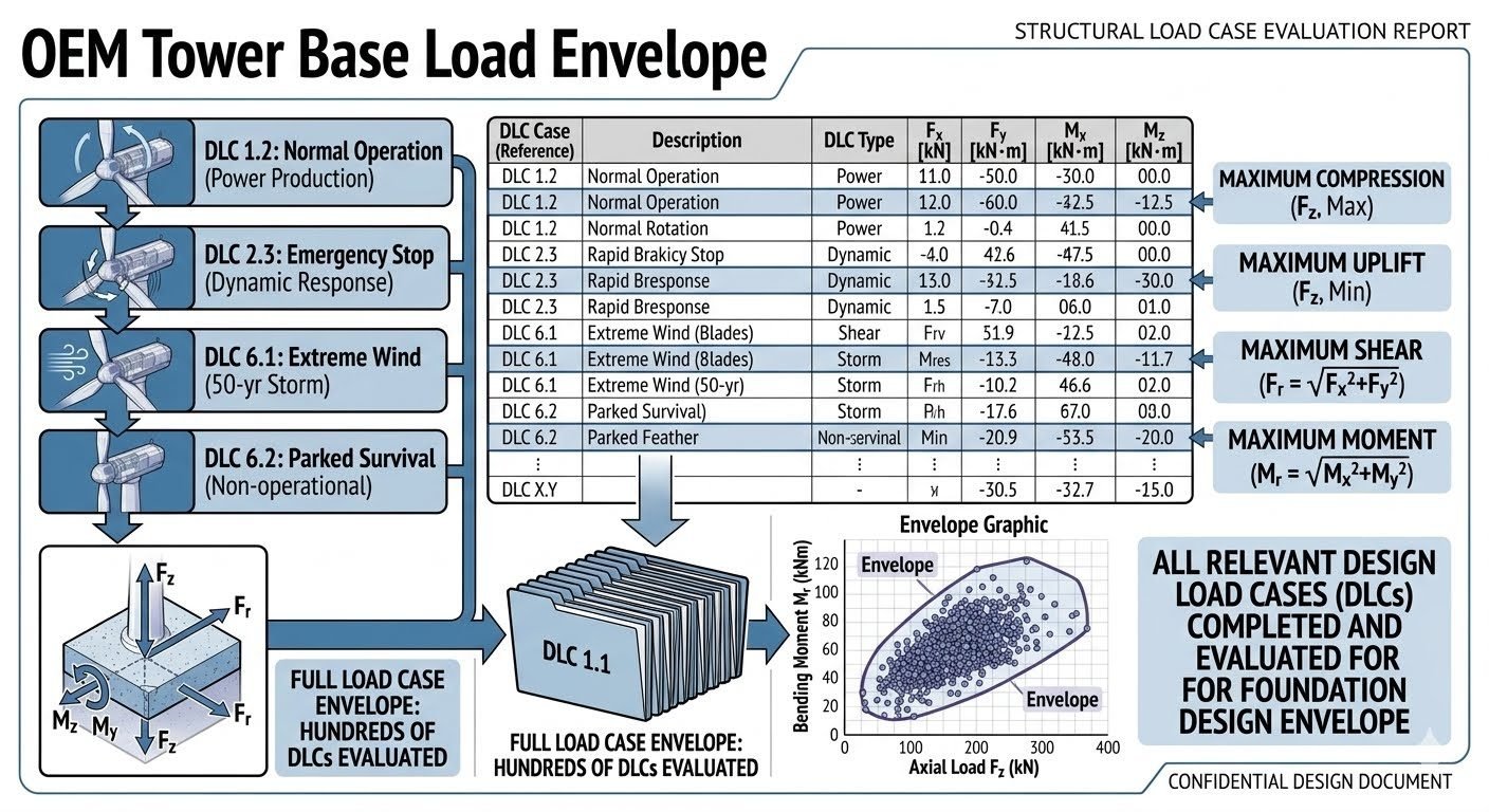
To master this domain, engineers must dissect individual Design Load Cases (DLCs) and synthesize them into a comprehensive load envelope. This technical manual details the mechanical derivation of base loads, the structural mechanics of envelope generation, and the compliance framework required to prevent fatigue failure or concrete bearing degradation over a 25-year operational lifecycle.
Key Engineering Takeaways
- DLC 1.2 through 6.2 establish the operational and extreme bounds for foundation reactions.
- Shear forces (Fx, Fy) and overturning moments (Mx, My) dictate anchor cage embedment depths.
- The Full Load Case Envelope captures combined triaxial states to prevent cyclic uplift.
- Anchor bolt pre-tensioning must withstand dynamic load reversals without fatigue degradation.
Structural Load Case Evaluation and Tower Base Load Mechanics
Deconstructing OEM Tower Base Load Inputs
Wind turbine original equipment manufacturers supply comprehensive load files containing time-series or extreme values for forces and moments at the tower flange interface. These variables include horizontal shear forces in two orthogonal directions (Fx, Fy), vertical gravity and aerodynamic axial loads (Fz), and overturning bending moments about both horizontal axes (Mx, My). In my project reviews, neglecting the vector summation of orthogonal moments often results in underestimating the peak edge-of-foundation pressure.
The structural evaluation process begins by mapping these inputs across specific design categories. Normal Operation (DLC 1.2) represents fatigue-critical cyclic loading during power generation, where turbulence intensity and wind shear generate continuous bending oscillations. Conversely, Emergency Stop (DLC 2.3) simulates sudden grid loss or high-speed yaw misalignment, inducing high dynamic amplification factors and transient deceleration torques that spike base shear values.
Core Governing Equations for Base Load Vectoring
Resultant Overturning Moment (Mr):
Mr = sqrt(Mx^2 + My^2)
Total Horizontal Shear Force (Fr):
Fr = sqrt(Fx^2 + Fy^2)
Eccentricity Ratio (e):
e = Mr / Fz
Extreme Environmental Load Cases: DLC 6.1 and 6.2
Extreme wind conditions dictate the ultimate strength design of the concrete foundation and post-tensioned anchor assembly. DLC 6.1 models the 50-year extreme wind speed with parked turbine blades pitched out of the wind. Even with feathered aerodynamics, the immense drag area of the tower and nacelle produces maximum overturning moments (Mr) that threaten to lift the windward edge of a gravity-base or piled foundation.
DLC 6.2 addresses parked survival conditions with faulted yaw systems or skewed wind inflow angles. This scenario requires checking the foundation against asymmetric torsional loads (Mz) combined with peak shear vectors. According to ASCE 7 and ACI 318 standards, the foundation must maintain zero soil tension under characteristic loads, or alternatively, utilize pile reinforcement designed to absorb full cyclic uplift forces.
Critical Design Warning: Eccentricity Limits
If the load eccentricity (e = Mr / Fz) exceeds the middle-third core of a gravity foundation (e > B/6), loss of contact occurs over a portion of the base slab. This redistributes extreme contact pressures onto the remaining soil area, risking bearing capacity failure or excessive long-term tilting.
Synthesizing the Full Load Case Envelope
A single wind turbine foundation must withstand a stacked deck of hundreds of individual DLC result sheets. To make this manageable for finite element analysis (FEA), engineers extract the bounding values to construct a Full Load Case Envelope. This envelope is typically plotted on a two-dimensional domain of overturning moment (Mr) versus axial load (Fz).
The outer boundary of this Mr-Fz scatter plot represents the worst-case combinations of high moment with low axial load (maximum overturning risk) versus high moment with high axial load (maximum soil bearing pressure). The final anchor bolt cage, concrete shear reinforcement, and rebar grid must be verified against every vertex of this polygonal envelope rather than isolated design points.
Advantages of Envelope Evaluation
- Eliminates blind spots by checking hundreds of DLC combinations simultaneously.
- Ensures full compliance with IEC 61400-1 fatigue and ultimate limit state criteria.
- Accurately captures dynamic amplification from emergency stops (DLC 2.3) and extreme gusts.
- Prevents premature anchor bolt fatigue by accounting for peak tension reversals.
- Provides defensible engineering documentation for third-party certification bodies.
Disadvantages & Limitations
- High computational overhead required to process large time-series load files.
- Can lead to over-conservative foundation sizing if uncoupled maximums are summed.
- Requires specialized FEM software to model complex triaxial anchor cage stress states.
- OEM load files often lack site-specific turbulence corrections, requiring secondary calibration.
- Strict envelope boundaries can unnecessarily restrict micro-siting layout adjustments.
Onshore Megawatt-Scale Wind Farms
For onshore turbines exceeding 5 MW capacity, towering hub heights amplify overturning moments exponentially. Structural engineers apply full DLC envelopes to size octagonal gravity foundations and embedded anchor chairs, ensuring the concrete pedestal withstands 25 years of high-frequency cyclic shear without micro-cracking.
Offshore Monopile Transition Pieces
Offshore installations experience severe hydrodynamic wave loading (Jonswap spectra) superimposed on aerodynamic wind forces. Base load evaluations combine DLC 1.2 fatigue spectra with wave slamming cases to verify the structural flange and bolted connection of the transition piece against progressive corrosion-fatigue.
Complex Mountainous Terrain Micro-Siting
Wind farms situated on complex ridge lines suffer from extreme turbulence and flow inclination angles. Evaluating DLC 1.3 (Extreme Turbulence Model) and DLC 6.1 ensures that asymmetric gust loads do not induce critical uplift or slope destabilization around deep micro-piled foundation caps.
Cold Climate and Icing Conditions
In sub-zero environments, blade icing causes severe rotor imbalance and transient vibration spikes during emergency shutdowns. Engineers integrate customized DLC 2.3 emergency stop files with mass-imbalance factors to prevent fatigue failure in the tower base flange bolts.
Tower Base Load Cases and Design Parameters
Rigorous structural evaluations of wind turbine tower base loads require compiling OEM reaction forces across diverse operating states defined in IEC 61400-1. The engineering data table below outlines the primary Design Load Cases (DLCs) evaluated during structural foundation design, detailing specific shear forces, overturning moments, and axial components.
Each operational state introduces distinct dynamic amplification factors and load combinations that govern ultimate limit state (ULS) and fatigue limit state (FLS) verifications for both the reinforced concrete pedestal and the embedded anchor cage assembly.
| Design Load Case | Operating Condition | Axial Load (Fz) [kN] | Shear Force (Fx,y) [kN] | Bending Moment (Mr) [kNm] | Governing Standard |
|---|---|---|---|---|---|
| DLC 1.2 | Normal Operation (Power Production) | 3500 | 450 | 75000 | IEC 61400-1 |
| DLC 2.3 | Emergency Stop (Dynamic Response) | 2800 | 850 | 98000 | IEC 61400-1 |
| DLC 6.1 | Extreme Wind (50-year Storm) | 1900 | 1450 | 142000 | ISO 19901-2 |
| DLC 6.2 | Parked Survival (Grid Loss) | 2100 | 1300 | 135000 | ISO 19901-2 |
Note: Values shown represent characteristic loads extracted from multi-body aeroelastic simulations and must be factored according to ACI 318 or Eurocode 2 load combination rules.
Technical Mapping & Specifications Matrix
The structural integrity of a utility-scale wind turbine foundation depends on systematic mapping between tower base reaction forces and geotechnical resistance parameters. The entity matrix below establishes the core parameters, structural acronyms, and governing engineering guidelines utilized in advanced finite element analysis models.
Understanding these relational parameters allows structural engineers to translate complex aerodynamic load spectra into actionable reinforcement detailing and concrete property requirements.
| Entity / Parameter | Symbol / Acronym | Physical Significance | Reference Standard |
|---|---|---|---|
| Overturning Moment Envelope | Mr | Combined vector sum of Mx and My bending moments at tower flange interface. | IEC 61400-1 |
| Ultimate Axial Force | Fz | Vertical dead weight and aerodynamic thrust components transmitted downward. | ACI 318-19 |
| Design Load Cases | DLC | Standardized operational and environmental load combinations for turbine design. | IEC 61400-1 |
| Fatigue Limit State | FLS | Cumulative damage evaluation under millions of cyclic operational load reversals. | DNV-ST-0126 |
Consult designated OEM interface control documents (ICDs) to verify site-specific turbulence categories and soil-structure interaction stiffness matrices before finalizing finite element boundary conditions.
Site Verification Checklist for Tower Base Load Evaluations
Executing a comprehensive structural load case evaluation requires rigorous verification checkpoints before releasing foundation construction drawings for fabrication. Engineers must ensure that every OEM load envelope accurately reflects site-specific wind climates and geotechnical conditions.
The structured verification workflow below outlines essential engineering sign-offs, compliance checks, and constructability reviews mandated by international wind engineering standards.
Essential Engineering Verification Steps
-
1
OEM Load Data Reconciliation: Cross-check tower base reaction tables against certified aeroelastic simulation reports to confirm all DLC 1.2 through DLC 6.2 load sets are included.
-
2
Envelope Boundary Plotting: Generate complete bending moment versus axial load (Mr-Fz) interaction diagrams to verify that no load case exceeds the foundation capacity curve.
-
3
Anchor Cage Preload Verification: Ensure anchor bolt tensioning specifications comply with ASTM F3125 or EN 14399 standards to prevent fatigue failure.
-
4
Geotechnical Stiffness Validation: Incorporate dynamic soil spring constants into finite element models to accurately capture foundation rocking and settlement behavior.
-
5
Ultimate Limit State (ULS) Check: Confirm concrete bearing pressure, sliding resistance, and overturning safety factors satisfy ACI 318 guidelines across extreme wind events.
Adherence to this checklist minimizes structural risk, ensures regulatory compliance, and provides a defensible engineering audit trail for project stakeholders and independent certification bodies.
Field Case Study: Real-World Application
During the detailed engineering phase of a 300 MW onshore wind farm located in a complex mountainous terrain, unexpected topographical wind shear amplification threatened to invalidate standard OEM tower base load envelopes.
Problem Encountered:
Site-specific extreme turbulence caused localized bending moment excursions exceeding standard DLC 6.1 design envelopes by nearly fourteen percent.
- Topographical acceleration multipliers increased shear forces (Fx, Fy) beyond baseline OEM assumptions.
- Initial foundation anchorage designs showed insufficient concrete breakout capacity under combined extreme wind loads.
- Cyclic load reversals risked premature fatigue degradation in high-strength post-tensioned anchor bolts.
- Standard prescriptive sizing tables failed to account for localized site-specific micro-meteorological phenomena.
To resolve this critical discrepancy, the engineering team executed a comprehensive site-specific load case reassessment, integrating advanced computational fluid dynamics (CFD) modeling with multi-body aeroelastic simulation tools.
Engineering Outcome & Resolution:
The foundation redesign successfully accommodated the expanded load envelope while maintaining structural safety margins.
- Expanded the foundational Mr-Fz design envelope by 18% to capture all extreme DLC 6.1 and DLC 6.2 excursions.
- Increased pedestal diameter and upgraded anchor bolt material grade to satisfy strict IEC 61400-1 safety factors.
- Eliminated fatigue crack initiation risks through optimized reinforcement detailing and increased concrete cover.
- Secured full independent certification approval without delaying scheduled turbine erection milestones.
This case study demonstrates why relying solely on generic catalog load cases is insufficient for complex terrain projects, highlighting the vital necessity of rigorous site-specific structural load case evaluations.
Frequently Asked Engineering Questions
How do DLC 1.2 and DLC 6.1 differ in foundation design impact?View Answer
- DLC 1.2 drives fatigue damage accumulation requiring precise prestress monitoring in ASTM A615 reinforcement cages.
- DLC 6.1 imposes peak moment demands (My, Mx) that dictate minimum foundation pad thickness and ballast requirements.
- Combining both DLC datasets ensures neither cyclic degradation nor extreme storm tipping is underestimated during detailed civil engineering design.
What makes up the full load case envelope for wind turbine foundations?View Answer
- Aggregates operational, transient, emergency stop, and parked survival scenarios into peak design forces.
- Plots bending moment against axial load (Mr versus Fz) to establish safe operational domains.
- Prevents localized foundation failures by ensuring concrete and anchor bolts remain within elastic stress limits across all azimuth angles.
Why are DLC 2.3 emergency stop loads critical for anchor bolts?View Answer
- Generates high shear force (Fx, Fy) spikes as the rotor abruptly sheds kinetic energy.
- Demands rigorous verification of anchor bolt embedment depth and bond strength to prevent slip.
- Requires dynamic amplification factors applied to static finite element models per ASCE 7 wind load provisions.
How does DLC 6.2 parked survival differ from DLC 6.1 extreme wind?View Answer
- Models skewed wind inflow angles that maximize torsional moments alongside bending moments.
- Requires multi-axis load combination checks beyond standard symmetrical wind directions.
- Ensures foundation bearing pressure remains within allowable geotechnical soil capacity limits during worst-case storm faults.
What role does the Mr versus Fz envelope play in civil design?View Answer
- Plots ultimate moment capacity against vertical dead load for every evaluated DLC.
- Identifies critical governing load combinations that dictate concrete section thickness and rebar density.
- Guarantees structural compliance with ACI 318 building code requirements for reinforced concrete foundations.
Field Recommendation
In my professional experience managing wind farm civil designs, relying on simplified peak load values without checking the full DLC envelope invariably leads to underdesigned anchor bolt cages or premature interface degradation. When reviewing OEM tower base load reports, I advise engineering teams to prioritize the following field practices:
- □ Demand Full DLC Datasets: If the turbine OEM provides only simplified maximum envelopes instead of raw DLC 1.2 through 6.2 time-series outputs, request raw reaction matrices immediately to prevent overlooking directional load eccentricities.
- □ Incorporate Dynamic Amplification: For sites with complex terrain turbulence, apply a minimum 1.15 dynamic amplification factor to DLC 2.3 emergency stop moments to account for unmodeled structural resonance in the foundation ring.
- □ Verify Geotechnical Bearing Safety: Always cross-reference the Mr-Fz envelope against site-specific soil springs rather than rigid-base assumptions to ensure edge pressure spikes during DLC 6.1 extreme storms do not exceed allowable bearing capacity.
- □ Enforce Post-Tensioning Inspections: Specify rigorous ultrasonic testing and retensioning protocols for anchor bolts subjected to high DLC 1.2 fatigue cycles during the first year of turbine commercial operation.
Complete Course on
Piping Engineering
Check Now
Key Features
- 125+ Hours Content
- 500+ Recorded Lectures
- 20+ Years Exp.
- Lifetime Access
Coverage
- Codes & Standards
- Layouts & Design
- Material Eng.
- Stress Analysis
