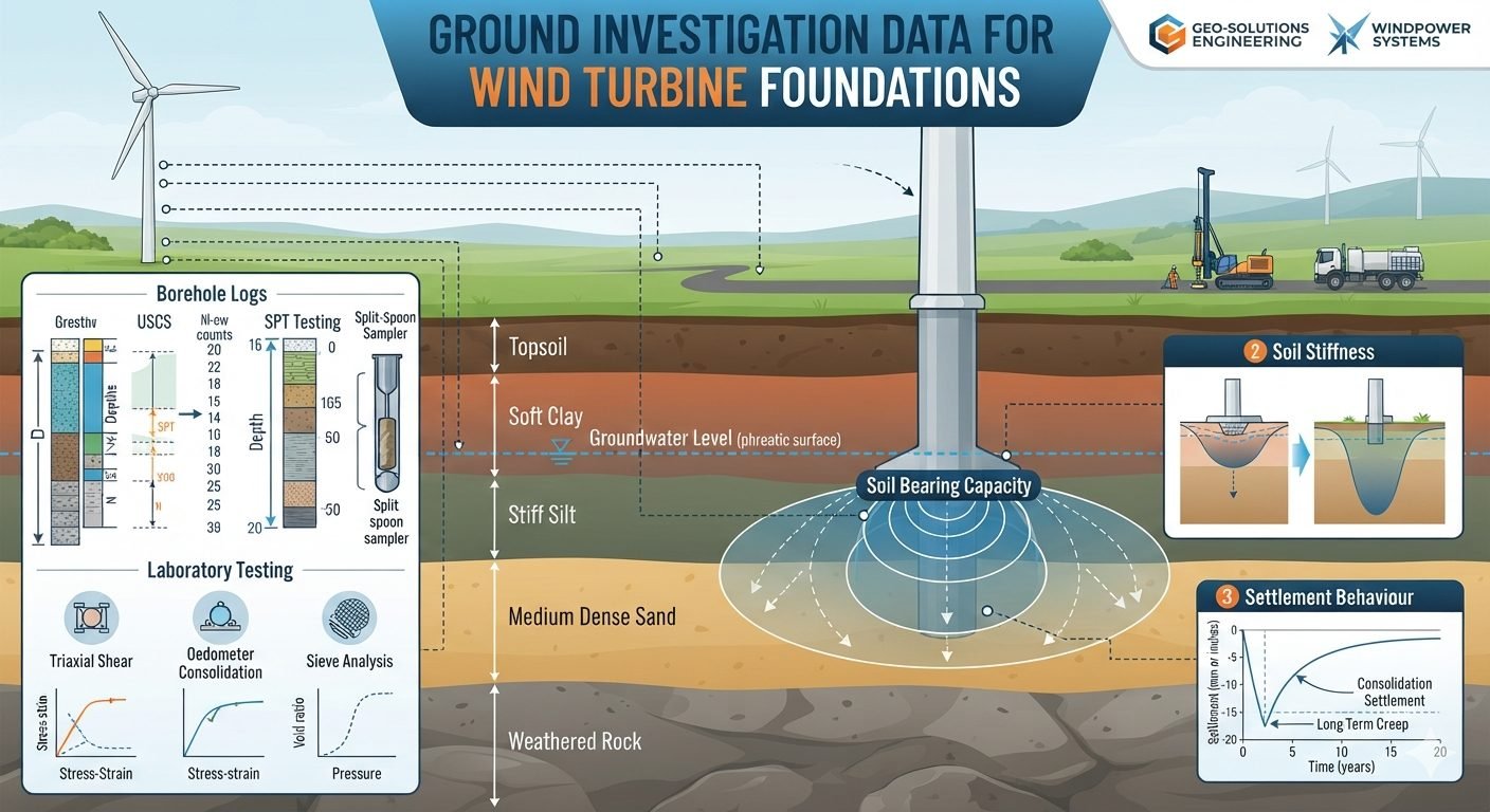
Wind Turbine Foundation Ground Investigation and Geotechnical Data Analysis
In my two decades of managing heavy industrial and renewable energy projects, I have repeatedly observed that the structural integrity of a multi-megawatt wind turbine tower depends entirely on the quality of its geotechnical foundation ground investigation. When we design massive gravity-base or piled foundations for wind turbines, we are not merely dealing with static dead loads; we are transferring massive overturning moments generated by dynamic wind shear forces directly into the earth. Understanding the true mechanical behavior of subsurface soils requires a rigorous campaign of field logging, in-situ penetration testing, and advanced laboratory soil mechanics.
Without precise geotechnical data regarding soil stratification, groundwater tables, and consolidation parameters, foundation designs risk excessive differential settlement or bearing capacity failure under cyclic wind loading. In this technical manual, I break down how borehole logs, standard penetration test blow counts, triaxial shear testing, and oedometer consolidation curves drive safe, code-compliant geotechnical engineering for modern wind energy installations.
Key Investigation Takeaways
- Borehole logging correlates elevation, Unified Soil Classification System groups, and moisture variations across all structural boring depths.
- Standard penetration test blow counts provide empirical correlations for internal friction angles and immediate elastic soil stiffness.
- Laboratory triaxial shear and oedometer testing define the stress-strain envelopes and long-term consolidation settlement parameters.
- Bearing capacity calculations establish the spatial pressure bulb beneath the base slab to prevent rotational or sliding failures.
Geotechnical Characterization and Subsurface Stratigraphy for Wind Turbine Foundations
Executing a reliable ground investigation for an onshore wind turbine site demands careful planning of borehole layouts across the turbine footprint. Typically, geotechnical engineers drill at least one primary boring at the exact turbine center to a depth exceeding the zone of significant stress influence, usually matching or exceeding the foundation diameter or active pile tip depth. Additional borings are placed radially to capture localized dipping bedrock or erratic alluvial lenses.
During drilling, field engineers record exact layer elevations, color changes, plasticity, and moisture conditions. The Unified Soil Classification System (USCS) provides the standardized naming convention, dividing soils into coarse-grained sands and gravels (symbolized by prefixes G and S) and fine-grained silts and clays (symbolized by M and C), modified by plasticity descriptors like high (H) or low (L). Groundwater observations are logged immediately upon striking free water and after stabilization periods to record true piezometric heads.
The stratigraphic profile typically transitions from surficial organic topsoil down through soft, compressible alluvial clays, stiff intermediate silt strata, medium dense granular sand layers, and finally terminates into competent weathered or unweathered rock. Each distinct stratum dictates specific load transfer mechanisms for the turbine foundation.
Standard Penetration Testing and Empirical Correlation
The Standard Penetration Test (ASTM D1586) is the backbone of in-situ geotechnical profiling. A standard split-spoon sampler is driven into the soil at specific depth intervals using a 63.5 kg hammer falling freely from a 760 mm height. The blow count required to drive the sampler through the final 300 mm of a 450 mm total penetration interval is recorded as the N-value.
In coarse-grained soils like sand and gravel, raw N-values are heavily influenced by overburden pressure. Geotechnical engineers apply correction factors to convert raw counts into N_160 values, accounting for hammer energy efficiency, borehole diameter, rod length, and effective overburden stress. These corrected blow counts directly correlate to relative density, drained internal friction angles, and elastic modulus.
SPT Correction and Friction Angle Relationships
Overburden Pressure Correction Factor (C_N):
C_N = min(2.0, sqrt(100 / sigma’_v0))
Where σ’{v0} represents the effective overburden pressure in kilopascals. Empirical estimates for granular friction angle (φ’) follow the correlation:
phi’ = sqrt(20 * N_160) + 20
In fine-grained cohesive soils, unconfined compressive strength and undrained shear strength (S_u) are often estimated from SPT blow counts, though laboratory testing remains essential for precise calibration because gravelly inclusions or high sensitivity can artificially skew dynamic penetration resistance.
Laboratory Soil Mechanics and Constitutive Modeling
Recovered undisturbed tube samples and disturbed bulk samples undergo rigorous laboratory characterization to establish stress-strain parameters. Sieve analysis and hydrometer testing yield grain-size distribution curves, confirming the percentage of fines and classifying soil grading characteristics. Atterberg limits testing determines liquid limit, plastic limit, and plasticity index, defining the moisture bounds within which cohesive soils exhibit plastic behavior.
Triaxial shear testing (ASTM D4767 for consolidated-undrained tests) subjects cylindrical soil specimens to isotropic cell pressures followed by axial deviatoric loading. The resulting stress-strain curves reveal peak and residual shear strengths, pore water pressure generation behavior, and drained or undrained shear strength envelopes (cohesion intercept c’ and friction angle φ’).
Critical Engineering Warning: Sample Disturbance
In soft to medium clay strata, extraction of thin-walled Shelby tubes can induce mechanical shear distortion and relieve in-situ total stresses. If laboratory oedometer and triaxial samples are not handled, sealed, and tested with strict adherence to stress-relaxation protocols, the measured yield stress and preconsolidation pressure will be artificially depressed, resulting in severely unconservative settlement predictions for heavy wind turbine towers.
Oedometer consolidation testing (ASTM D2435) subjects confined disc specimens to incremental vertical loads, measuring dimensional changes over time. Plotting void ratio versus logarithm of effective stress yields the compression index (C_c), swelling index (C_s), and preconsolidation pressure (σ’_p). These parameters allow engineers to predict both immediate elastic settlement and time-dependent primary consolidation settlement.
Bearing Capacity and Settlement Analysis for Wind Turbines
The ultimate bearing capacity of a wind turbine foundation represents the maximum contact pressure the ground can support before experiencing shear failure. Evaluated via Terzaghi or Meyerhof bearing capacity equations, the analysis incorporates foundation embedment depth, width, shape factors, and groundwater table depth modifications. The resulting stress distribution forms a bulb of high vertical stress beneath the base slab, extending downward to a depth where induced stresses drop to ten percent of the applied footing pressure.
Total settlement comprises three distinct components: immediate distortion settlement occurring concurrently with construction, primary consolidation settlement driven by pore water expulsion in cohesive layers, and secondary compression (creep) occurring under constant effective stress over decades of turbine operation. Displacement versus time curves generated from oedometer data ensure that angular distortion across the massive octagonal or circular concrete pad remains within turbine manufacturer limits, preventing excessive tower tilt that could damage mechanical drive trains or turbine yaw systems.
Engineering Advantages
- Optimized Foundation Sizing: Accurate SPT and triaxial data prevent over-designing concrete gravity bases, reducing capital material costs.
- Risk Mitigation: Early identification of soft clay strata and perched groundwater tables prevents catastrophic differential settlement during turbine operation.
- Standard Compliance: Full adherence to ASTM and ISO standards ensures bankable geotechnical reports for project financing.
- Dynamic Load Modeling: Laboratory stress-strain curves supply exact soil spring stiffness values for finite element modal analysis of tower resonance.
- Excavation Feasibility: Comprehensive borehole logs delineate hard rock boundaries versus rippable soil, improving earthwork contractor bidding accuracy.
Engineering Disadvantages
- High Initial Capital Outlay: Extensive deep drilling and multi-stage triaxial testing require significant upfront investigation budgets before construction permits.
- Schedule Bottlenecks: Laboratory consolidation tests and multi-stage shear programs can take several weeks to complete, delaying final design sign-off.
- Spatial Variability Risk: Point-source borehole data can miss erratic karst features or localized soil pockets located between boring locations.
- Mobilization Logistics: Heavy drilling rigs face severe access challenges in remote mountainous or marshy wind farm terrain, requiring specialized tracked equipment.
- Disturbance Artifacts: Undisturbed sampling in cohesionless sands or sensitive sensitive clays is technically challenging and prone to sample alteration.
Onshore Gravity-Base Foundation Design on Layered Alluvium
Large onshore wind farms constructed over glacial till and alluvial plains rely heavily on borehole logs and SPT blow counts to size shallow octagonal concrete gravity slabs. By mapping stiff silt layers overlying soft clay, geotechnical engineers determine whether bearing pressure bulbs remain within competent strata, preventing excessive rotational tilting under cyclic overturning moments from multi-megawatt rotors.
Piled Foundation Design in Soft Compressible Marine Clay
In coastal or marshy wind turbine installations where soft clay extends to considerable depths, direct foundation support is impossible without deep piling. Oedometer consolidation curves and triaxial shear test parameters govern the design of driven steel pipe piles or bored cast-in-place shafts, calculating skin friction capacity and negative skin friction downdrag resulting from ongoing primary consolidation settlement.
Offshore Monopile and Jacket Foundation Seabed Profiling
Offshore wind turbine installations require specialized marine geotechnical investigations utilizing seabed CPT (cone penetration testing) and offshore drilling rigs. Shear strength profiling of sub-seabed sand and clay layers directly informs the wall thickness, driving embedment depth, and cyclic lateral load-displacement response of large-diameter monopiles or pin-piled jacket transition pieces.
Complex Ridge and Mountainous Terrain Micro-Siting
Wind turbines situated along high-elevation mountain ridges often encounter shallow weathered bedrock interspersed with colluvial debris slopes. Detailed geological logging and rock quality designation (ASTM D6032) allow engineers to design rock-anchored spread footings or micro-pile socketed foundations that safely transfer massive shear loads into sound bedrock without excessive excavation.
Geotechnical Parameters for Wind Turbine Foundation Design
In my foundation engineering practice, translating raw borehole logs into reliable design parameters requires rigorous correlation methods. Geotechnical ground investigation data for wind turbine foundations provides the core mechanical properties needed to evaluate overturning stability, sliding resistance, and dynamic load transfer from towering tubular steel wind turbine towers. Because wind turbines impose massive eccentric overturning moments alongside cyclic horizontal shear forces, structural and geotechnical engineers must carefully evaluate the variability of subsurface strata across the entire pad footprint.
The engineering data table below outlines the typical geotechnical parameters extracted from standard penetration test (ASCE compliant procedures), laboratory triaxial testing, and oedometer consolidation runs. These values dictate the allowable bearing pressure, dynamic subgrade reaction modulus, and long-term settlement projections necessary for ASTM standard gravity-base or piled foundation designs.
| Stratum Layer | USCS Classification | Typical SPT (N-value) | Undrained Shear Strength | Design Bearing Capacity |
|---|---|---|---|---|
| Topsoil / Organic Overburden | OL / PT | 2 – 4 | Not Applicable (Stripped) | Rejected (Unsuitable) |
| Soft Alluvial Clay | CH / CL | 4 – 8 | 25 – 50 kPa | 75 – 120 kPa |
| Stiff Glacial Silt | ML | 12 – 22 | 100 – 180 kPa | 200 – 300 kPa |
| Medium Dense Sand | SP / SW | 20 – 35 | Friction Angle (32°-36°) | 350 – 500 kPa |
| Weathered Bedrock | Weathered Rock | > 50 (Refusal) | > 300 kPa | > 600 kPa |
Note: All values must be verified via site-specific cone penetration testing (CPTu) and laboratory consolidation testing before final geotechnical sign-off.
Technical Mapping & Specifications Matrix
Modern wind farm developments require a standardized technical vocabulary to bridge the gap between field geotechnical investigations and structural foundation design. In my structural design reviews, mapping physical soil parameters to computational finite element models ensures that turbine towers maintain strict rotational stiffness limits. Excessive differential settlement can induce severe fatigue loads on the wind turbine generator blades and internal drive components.
The technical mapping matrix below correlates core geotechnical entities, standardized testing procedures, and governing engineering associations. By aligning field exploration methodologies with ISO and ASTM standards, design teams eliminate ambiguity in soil-structure interaction calculations for onshore wind turbine installations.
| Entity / Parameter | Standard Test Method | Governing Code | Design Function |
|---|---|---|---|
| Standard Penetration Test (SPT) | Split-Barrel Driving (ASTM D1586) | ASTM International | Evaluates in-situ density and relative stiffness of granular and cohesive soils. |
| Triaxial Shear Strength | Consolidated Undrained (CU) Triaxial | ASTM D4767 | Derives cohesion intercept and internal friction angle for bearing capacity. |
| Oedometer Consolidation | One-Dimensional Compression | ASTM D2435 | Determines preconsolidation pressure and primary/secondary settlement rates. |
| Soil Classification | Unified Soil Classification System | ASTM D2487 | Categorizes soil type for drainage, frost susceptibility, and excavation safety. |
Matrix verification guarantees compliance with international wind turbine foundation design standards and minimizes long-term operational tilt risks.
Site Verification Checklist for Ground Investigation Data
Ground investigation data validation requires a meticulous, step-by-step auditing protocol before structural engineering calculations commence. In my professional oversight of large wind farm projects, accepting raw borehole logs without rigorous quality control frequently leads to catastrophic foundation tilting or excessive long-term settlement.
Use the structured site verification checklist below to audit geotechnical field reports, laboratory test certificates, and stratigraphic profiles. Every checkpoint ensures that your wind turbine foundation design rests on verified, code-compliant geotechnical parameters.
Geotechnical Audit & Borehole Verification Checkpoints
-
Borehole Depth Adequacy: Verify that exploratory boreholes extend to a minimum depth of 1.5 to 2 times the proposed foundation diameter or reach competent rock refusal.
-
SPT Energy Calibration: Confirm that Standard Penetration Test hammer energy ratios (ERr) are recorded and corrected to N60 standards in accordance with ASTM D1586.
-
Groundwater Level Monitoring: Ensure piezometer readings account for seasonal fluctuations and artesian pressures across soft clay and silt strata.
-
USCS Classification Accuracy: Cross-check sieve analysis and Atterberg limit test results against borehole visual classifications for consistency.
-
Triaxial Test Confinement: Verify that confining pressures used in Consolidated Undrained (CU) testing bracket the actual in-situ overburden and structural loads.
-
Consolidation Curve Verification: Audit oedometer test void-ratio versus stress curves to confirm preconsolidation pressure and predict primary settlement accurately.
Completing this verification checklist ensures full compliance with ASCE guidelines and mitigates geotechnical risks throughout the 25-year operational lifecycle of the wind turbine generator.
Field Case Study: Real-World Application
During the construction of a 3.4 MW wind farm on a complex alluvial plain, unexpected geotechnical variations threatened the structural integrity of multiple turbine foundations. In my role as lead structural consultant, I evaluated site investigation discrepancies where initial borehole logs failed to capture localized soft clay pockets underlying stiff silt strata.
Field Problem: Unforeseen Soft Clay and Excessive Settlement Risks
Initial preliminary geotechnical reports indicated uniform stiff silt and medium-dense sand across the entire project site, leading the design team to propose standard shallow gravity-base foundations. However, pre-construction cone penetration testing and supplemental borehole logs revealed significant anomalies.
- A localized 4-meter thick pocket of soft, highly compressible organic clay was discovered directly beneath Turbine Location 12.
- Groundwater table monitoring indicated hydrostatic pressure heads sitting merely 0.8 meters below the proposed excavation subgrade.
- Preliminary oedometer consolidation testing showed high compression indices (Cc > 0.35) capable of inducing differential settlements exceeding allowable turbine tilt tolerances.
- Standard penetration test blow counts dropped sharply from N = 22 in the upper silt to N = 3 within the soft clay layer.
Field Outcome: Optimized Foundation Redesign and Successful Mitigation
Prompt identification of the subsurface strata anomalies allowed our engineering team to implement immediate design modifications before concrete pouring commenced, ensuring long-term structural stability.
- Redesigned Turbine Location 12 foundation from a shallow gravity pad to a rigid piled foundation supported by driven steel H-piles anchored into weathered bedrock.
- Incorporated comprehensive wick drains and surcharging protocols to accelerate primary consolidation in surrounding secondary turbine pads.
- Updated finite element soil-structure interaction models using site-specific triaxial shear parameters, confirming that maximum foundation rotation remained well below the 0.004 radians operational limit.
- Saved the project an estimated 450,000 in potential remediation costs and eliminated long-term turbine fatigue risks.
This case study underscores why thorough ground investigation data for wind turbine foundations remains paramount. Relying on generalized regional geology without comprehensive borehole logs and lab testing exposes renewable energy projects to severe structural distress and operational downtime.
Frequently Asked Engineering Questions
How do standard penetration test blow counts dictate wind turbine base sizing?
SPT blow counts establish the in-situ relative density of granular soils and consistency of cohesive layers directly beneath massive gravity bases.
- Low N-values in soft clay trigger deep settlement concerns requiring pile support.
- High N-values in dense sand provide high allowable bearing pressures for shallow spread footings.
- Values feed directly into ASCE settlement prediction models.
What role does triaxial shear testing play in dynamic overturning stability?
Triaxial testing isolates effective cohesion and friction angles under simulated cyclic wind loading conditions.
- Provides critical shear strength parameters for circular slip failure checks.
- Accounts for pore water pressure generation during rapid turbine yaw movements.
- Validates Mohr-Coulomb strength envelopes used in finite element geotechnical software.
Why is oedometer consolidation testing critical for clay-heavy wind farm sites?
Wind turbines demand strict angular tilt tolerances to prevent mechanical fatigue in the tower nacelle.
- Measures primary consolidation rates and secondary creep deformation in fine-grained strata.
- Determines preconsolidation pressure to verify if soils are overconsolidated.
- Calculates long-term differential settlement across large octagonal concrete foundation pads.
How do borehole stratigraphic profiles dictate deep versus shallow foundation selection?
Stratigraphic mapping reveals layer thickness variations across the multi-megawatt turbine layout.
- Shallow depths to competent bedrock favor gravity spread footings with excavation.
- Thick soft clay lenses necessitate driven steel piles or drilled shafts to transfer loads.
- Groundwater table mapping highlights dewatering requirements during deep excavation phases.
What safety factors apply when deriving soil bearing capacity from field logs?
Dynamic cyclic overturning moments require rigorous ultimate limit state safety factors.
- Minimum safety factor of 3.0 applied to static bearing capacity calculations.
- Reduction factors enforced for eccentric and inclined wind-induced foundation loads.
- Compliance maintained with ISO 19901-4 standards for offshore and onshore wind structures.
Field Recommendation
Based on my two decades of reviewing geotechnical site characterizations for heavy industrial wind infrastructure, making the right ground investigation decisions preserves structural integrity and controls construction expenditure. Implement these specific engineering judgments on your next project:
- If borehole logs reveal erratic soft clay pockets exceeding five meters in depth beneath proposed gravity pads, mandate immediate deep probe testing and switch to driven pile caps to prevent long-term differential settlement tilting the nacelle.
- If SPT blow counts in granular strata drop below 10 within the active pressure bulb zone, reject shallow spread footing designs and specify vibro-compaction ground improvement or deep drilled shafts to transfer loads to competent bedrock.
- If triaxial shear testing indicates low effective friction angles under saturated cyclic conditions, increase the foundation base diameter by at least 15 percent to enhance the overturning moment safety factor against extreme storm events.
- If oedometer consolidation curves show high secondary compression indices in organic silt layers, enforce a mandatory pre-loading waiting period with wick drains before erecting the tower superstructure.
Complete Course on
Piping Engineering
Check Now
Key Features
- 125+ Hours Content
- 500+ Recorded Lectures
- 20+ Years Exp.
- Lifetime Access
Coverage
- Codes & Standards
- Layouts & Design
- Material Eng.
- Stress Analysis
