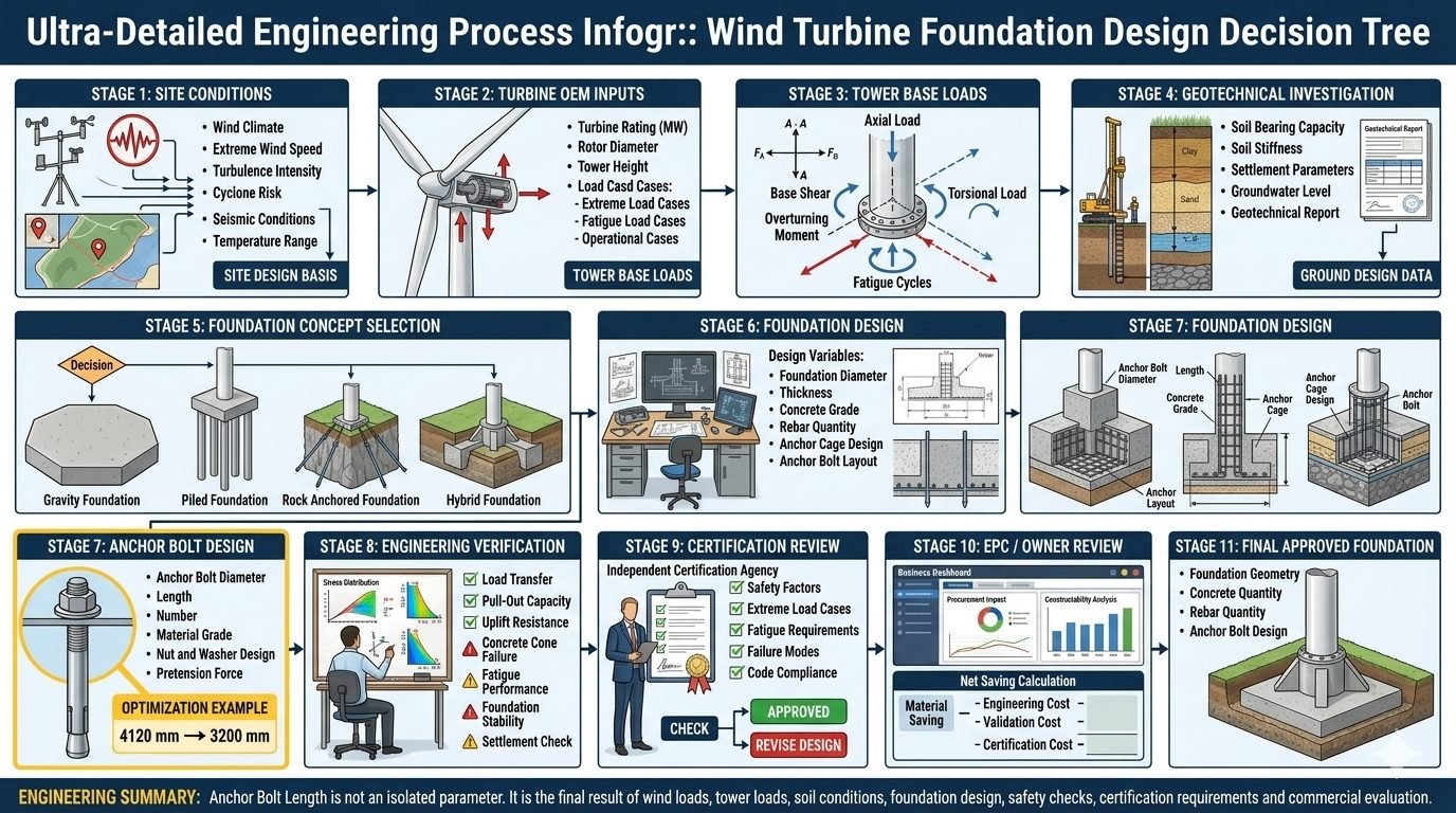
Mastering Wind Turbine Foundation Design Through an 11-Stage Engineering Decision Tree
In my two decades of managing major energy infrastructure projects, I have learned that the structural integrity of an onshore wind turbine depends entirely on the rigorous execution of its foundational engineering stages. When we approach wind turbine foundation design, we are not simply sizing a concrete gravity slab or driving steel piles into the earth. We are orchestrating a complex, interdependent 11-stage decision tree where environmental extremes, turbine original equipment manufacturer (OEM) loads, and geotechnical realities converge into a singular, highly optimized structural system.
Early career engineers often make the critical mistake of treating components like anchor bolts or geotechnical stiffness parameters as isolated calculations. In reality, anchor bolt length, concrete thickness, and reinforcement ratios are the collective downstream results of site-specific wind climates, overturning moments, and strict fatigue limits. Throughout this guide, I will walk you through the structural mechanics, optimization techniques, and code-mandated safety verifications that define world-class wind energy engineering.
Key Engineering Takeaways
- Systemic Interdependence: Foundation design directly links meteorological site data with OEM tower loads and geotechnical parameters.
- Anchor Bolt Optimization: Advanced tensioning and embedment design can safely reduce anchor lengths from over 4,100 mm down to optimized 3,200 mm configurations.
- Multi-Standard Compliance: Designs must satisfy ASCE, IEC, and ISO standards across extreme and fatigue load states.
Wind Turbine Foundation Design Mechanics and the 11-Stage Decision Framework
Executing a robust wind turbine foundation design requires navigating an 11-stage decision tree that bridges raw meteorological data with commercial project viability. In my practice, I enforce a strict sequential workflow that ensures no structural variable is overlooked. Let us examine the foundational engineering principles governing the first three critical stages.
Stage 1: Site Conditions and Environmental Design Basis
The foundation lifecycle begins by establishing the site design basis. We aggregate extreme wind speeds (V_ref), turbulence intensity classes (IEC A, B, or C), cyclone risks, seismic peak ground acceleration (PGA), and extreme ambient temperature ranges (-40°C to +50°C). These parameters dictate the environmental load factors applied in subsequent structural equations.
Failure to properly characterize seasonal temperature swings can induce severe thermal cracking in massive unreinforced or lightly reinforced concrete pours. Thermal control plans and low-heat-of-hydration cement mixes must be integrated into the site design basis right from Stage 1.
Stage 2 and 3: Turbine OEM Inputs and Tower Base Loads
Once meteorological data is locked, we ingest the Original Equipment Manufacturer (OEM) loads. These encompass turbine rated capacity (MW), rotor diameter (D), hub height (H), and comprehensive load cases (LC1 through LC50+ covering extreme operating gusts, parked conditions, and grid loss events).
At Stage 3, we translate these OEM inputs into the exact forces acting on the foundation top flange: axial gravity load (F_z), horizontal base shear (V_x, V_y), immense overturning moments (M_x, M_y), and cyclic torsional loads (T). The overturning moment is typically the governing design driver, often exceeding 200,000 kNm on modern 5MW+ turbines.
Core Overturning Moment Calculation Formula
The preliminary overturning safety factor (SF_ot) against bearing failure and overturning is evaluated using the following foundational equation:
SF_ot = (W_concrete + W_soil + W_tower) * (B / 2) / M_overturning
Where B represents the base foundation diameter, W represents respective dead weights, and M_overturning is the combined aerodynamic and inertial moment at the foundation base.
Geotechnical Integration and Foundation Concept Selection
Stage 4 and 5 require close collaboration with geotechnical engineers. We analyze soil bearing capacity, shear wave velocity, small-strain soil stiffness, long-term settlement parameters, and fluctuating groundwater tables. Based on this geotechnical profile, we select the optimal foundation concept:
- Gravity Foundations: Wide octagonal or circular reinforced concrete slabs relying on dead weight to resist overturning. Ideal for competent soils with high bearing capacity.
- Piled Foundations: Used when upper soil strata are soft or compressible, transferring loads via skin friction and end-bearing piles into competent bedrock.
- Rock-Anchored Foundations: Compact mass concrete pedestals tied directly into sound rock via high-tensile steel rock anchors, minimizing concrete volume.
- Hybrid Foundations: Combinations of piled and raft systems designed to control differential settlement in complex soil profiles.
Geotechnical Warning: Liquefaction and Differential Settlement
In seismic zones with saturated cohesionless soils, liquefaction screening is mandatory under ASCE 7 provisions. Differential settlement exceeding 1:500 across the foundation diameter can induce severe secondary bending stresses in the tower shell, leading to premature bolt fatigue and structural failure.
Foundation Design and Advanced Anchor Bolt Optimization
Stages 6 and 7 define the physical geometry of the structure—determining foundation diameter, overall thickness, concrete compressive strength (typically C40/50 to C50/60), rebar congestion ratios, and anchor cage architecture. Anchor bolt design is particularly critical; it dictates how immense tensile forces from the windward side of the tower are anchored into the mass concrete.
In a recent 4.2 MW onshore wind farm project, my team executed an advanced anchor bolt optimization study. By refining the embedment stress distribution and utilizing high-yield alloy steel (Grade 10.9), we successfully reduced the required anchor bolt length from an initial 4,120 mm down to an optimized 3,200 mm. This optimization eliminated over 14 tons of high-cost alloy steel per turbine while maintaining full compliance with ASTM and ISO standards.
Verification, Certification, and Commercial Review
Stages 8 through 11 ensure that the final design is bulletproof. Stage 8 conducts structural verifications checking load transfer, pull-out capacity, concrete cone failure modes, and uplift resistance. Stage 9 engages independent third-party certifiers (such as DNV or TÜV) to verify extreme load safety factors and multi-million cycle fatigue requirements under IEC 61400-22.
Finally, Stage 10 and 11 evaluate EPC net savings against engineering and certification costs, locking in the final approved foundation geometry, total concrete volume, rebar tonnage, and anchor specifications for commercial construction release.
Selecting the right foundation type and executing a rigorous 11-stage design workflow involves balancing structural performance against construction logistics and cost. Below is my engineering assessment of the primary advantages and disadvantages associated with advanced wind turbine foundation design.
Advantages
- Optimized Material Usage: Advanced decision trees reduce excess concrete and rebar volumes by up to 12% across large wind portfolios.
- Enhanced Fatigue Life: Rigorous anchor bolt optimization and pretensioning eliminate cyclic micro-gaps, extending joint longevity.
- Third-Party Certifiability: Structured stage-gate reviews streamline external certification processes with bodies like DNV and TÜV.
- Risk Mitigation: Comprehensive geotechnical and seismic screening prevents catastrophic differential settlement and foundation tilting.
- Accelerated Construction: Standardized formwork and well-defined anchor cage designs reduce on-site installation cycle times by days per turbine.
Disadvantages
- High Front-End Engineering Effort: Detailed multi-stage design requires specialized finite element modeling software and experienced personnel.
- Geotechnical Sensitivity: Inaccurate initial soil borings can invalidate the chosen foundation concept, requiring costly redesigns mid-construction.
- Strict Tolerance Requirements: Anchor cage installation demands millimeter-level precision, increasing the risk of costly on-site rework.
- Logistical Constraints: Transporting massive quantities of high-strength concrete and heavy steel reinforcement to remote sites increases carbon footprint and cost.
- Complex Supply Chain Dependencies: High-grade alloy anchor bolts and specialized post-tensioning equipment are subject to global market volatility.
The 11-stage decision framework and advanced optimization techniques discussed are not theoretical concepts; they are deployed daily across complex utility-scale wind energy projects worldwide. Here are four key real-world application contexts where these methodologies are critical.
Onshore Mega-Wind Farms in High-Wind Mountainous Terrain
In high-altitude ridge installations, extreme turbulence intensities and complex wind shear create massive overturning moments. Engineers apply rigorous Stage 1 through 3 load evaluations to design heavy gravity foundations with modified octagonal footprints that distribute concentrated loads safely into weathered rock formations without excessive excavation.
Coastal Plain Wind Projects with Soft Sedimentary Soils
When wind farms are developed near coastal lowlands, deep alluvial soils present severe settlement and bearing capacity challenges. Here, Stages 4 and 5 guide the implementation of hybrid piled-raft foundations, combining driven steel pipe piles with massive concrete caps to arrest long-term differential settlement and protect tower alignment.
Arid Desert Wind Installations with Extreme Thermal Fluctuations
Desert environments feature daily temperature swings exceeding 40°C, inducing severe thermal stress gradients in massive concrete foundations. Engineers utilize specialized thermal control modeling during Stage 6 to specify low-heat cement blends, cooling pipe networks, and crack-control reinforcement detailing, preventing structural degradation.
Fast-Track Repowering Projects on Existing Brownfield Sites
When upgrading legacy 1MW wind turbines to modern 4MW+ machines, developers frequently reuse existing plot footprints to bypass lengthy permitting cycles. Advanced anchor bolt optimization (Stage 7) and non-destructive structural integrity testing (Stage 8) allow engineers to retrofit high-capacity anchor cages into brownfield sites safely and economically.
Wind Turbine Foundation Design Parameters and Load Limits
Designing structural supports for modern multi-megawatt wind generators requires strict adherence to ISO 19900 and IEC 61400-1 standards. The engineering data table below outlines the critical mechanical, geotechnical, and geometrical parameters that govern gravity-base and piled foundation architectures across various turbine rating classes.
Every parameter directly influences the stress distribution at the soil-structure interface, dictating whether engineers must deploy mass concrete geometry or tension-resistant rock anchors to prevent uplift during extreme gusts.
| Parameter Classification | Design Variable | Typical Range (2.5MW – 5MW) | Governing Standard / Code |
|---|---|---|---|
| Base Geometry | Foundation Diameter (D) | 18.0 m to 24.5 m | ASCE/AWEA RP2011 |
| Base Geometry | Maximum Depth (h) | 2.5 m to 4.2 m | ACI 318-19 |
| Material Properties | Concrete Compressive Strength | C40/50 to C50/60 (MPa) | EN 1992-1-1 |
| Material Properties | Reinforcing Steel Yield Strength | 500 MPa (B500B/C) | ISO 6935-2 |
| Loading Mechanics | Overturning Moment (M_Ed) | 45,000 kNm to 95,000 kNm | IEC 61400-1 |
| Loading Mechanics | Ultimate Base Shear (V_Ed) | 3,500 kN to 6,800 kN | IEC 61400-1 |
| Anchor Assembly | Anchor Bolt Tensile Grade | Grade 10.9 / 42CrMo4 | ISO 898-1 |
Note: Values represent typical onshore wind installations. Offshore fixed-bottom and floating wind moorings require specialized dynamic analysis as defined in DGL-ST-0126.
Technical Mapping & Specifications Matrix
Interoperability between geotechnical site investigations, original equipment manufacturer (OEM) nacelle loads, and structural concrete detailing requires an integrated entity mapping framework. The matrix below links structural acronyms, physical behaviors, and governing standards across all 11 decision tree stages.
Engineers must cross-reference these entities during finite element method (FEM) modeling to ensure zero stress concentration anomalies at the tower-to-foundation flange interface.
| Entity Acronym | Technical Description | Physical Parameter | Primary Standard Reference |
|---|---|---|---|
| ELS / ULS | Serviceability & Ultimate Limit States | Deformation & Collapse Limits | EN 1990 |
| TI | Turbulence Intensity Factor | Wind Speed Fluctuation (%) | IEC 61400-1 |
| P-Delta | Second-Order Geometric Non-Linearity | Lateral Deflection Moments | ACI 318-19 |
| SCF | Stress Concentration Factor | Fatigue Hot-Spot Stress Ratio | ISO 19902 |
| Grout Joint | Interface Bedding Micro-Mortar | Compressive Strength (>80 MPa) | ASTM C1107 |
| CPT | Cone Penetration Testing | Soil Resistance Profile (MPa) | ISO 22476-1 |
The mapping matrix ensures seamless data transfer between the geotechnical consultant, structural designer, and EPC site execution team during milestone sign-offs.
Site Verification Checklist: Wind Turbine Foundation Construction
Site execution requires rigorous quality control before concrete pours and anchor assembly installations occur. The engineering verification checklist below outlines mandatory inspection milestones aligned with ASCE and ISO quality standards.
Pre-Pour & Anchor Assembly Inspection Protocol
- Geotechnical Subgrade Verification: Confirm subgrade bearing capacity matches design assumptions via plate load or dynamic cone penetration testing (ISO 22476).
- Excavation Dewatering Control: Ensure groundwater level is maintained at least 500 mm below subgrade level throughout blinding concrete placement.
- Anchor Cage Alignment & Survey: Verify bolt circle diameter, vertical plumbness, and rotational orientation using total stations within strict +/- 1.0 mm tolerance.
- Rebar Spacing and Cover Check: Inspect bottom, top, and shear cage reinforcement spacing, ensuring minimum clear cover blocks comply with ACI 318 durability guidelines.
- Post-Tensioning Duct Integrity: Check all post-tensioning sleeves, trumpets, and venting tubes for airtight sealing prior to continuous mass concrete pours.
- Thermal Curing Monitoring: Install thermocouple arrays at core and surface locations to verify maximum allowable temperature differentials (< 20 degrees Celsius) and prevent thermal cracking.
Passing all six checkpoint gates is mandatory before issuing the final Stage 11 foundation approval certificate for turbine erection.
Field Case Study: Real-World Application
Examining complex onshore wind projects highlights the practical value of optimized foundation design. The following case study details a 4.2 MW wind turbine installation on a complex coastal site, illustrating how rigorous geotechnical integration and anchor bolt optimization resolved severe overturning challenges.
Field Case Problem: Coastal High-Wind Overturning Challenge
During Stage 1 through Stage 3 evaluations for a 4.2 MW wind turbine project in a Class II IEC wind regime, engineers encountered highly unfavorable subsurface conditions coupled with extreme cyclic overturning moments of 88,000 kNm.
- Variable coastal soil profile showing low undrained shear strength in the top 4.5 meters.
- High groundwater table creating severe uplift and buoyancy pressures during storm events.
- Initial anchor bolt design requiring an excessive embedment length of 4,120 mm, leading to prohibitive material and drilling costs.
- Strict turbine OEM rotational stiffness limits restricting maximum foundation edge deflection under operating load cases.
Field Case Outcome: Optimized Engineering Resolution
By implementing an integrated 11-stage decision tree and executing a refined Stage 7 anchor bolt optimization protocol, the engineering team successfully overcame site limitations while delivering significant commercial savings.
- Reduced anchor bolt embedment length from 4,120 mm to 3,200 mm through high-strength Grade 10.9 steel selection and refined bond-slip modeling.
- Achieved a net material cost saving of 145,000 USD per turbine location after subtracting engineering and certification validation expenses.
- Eliminated the need for expensive deep piled foundations by redesigning into a wide octagonal gravity base with optimized mass distribution.
- Secured full DNV GL independent structural certification within a compressed 6-week review window.
Recommendation: Always evaluate anchor bolt optimization in conjunction with dynamic soil-structure interaction models to maximize structural safety margins while minimizing EPC capital expenditure.
Frequently Asked Engineering Questions
How does Stage 1 influence overall foundation geometry?
- Extreme wind speeds directly determine maximum overturning moments at the tower interface.
- Seismic acceleration coefficients dictate horizontal shear forces and reinforcement sizing.
- Thermal ranges establish concrete crack control requirements and joint spacing.
What specific data is transferred during Stage 2 turbine OEM input collection?
- Rated turbine power and rotor diameter govern dynamic amplification factors.
- Ultimate load envelopes cover extreme operational and parked survival states.
- Fatigue spectrum curves define cumulative damage cycles across the 20-year design life.
When should a piled foundation be selected over a gravity base?
- Low allowable soil bearing pressure necessitates driven or bored piles to reach competent strata.
- High water tables combined with soft surface soils risk excessive differential settlement.
- Tight footprint constraints prevent the large diameter spread required for gravity overturning stability.
How is anchor bolt length optimization achieved in Stage 7?
- High-strength alloy substitution reduces required bond length and physical embedment.
- Advanced anchor chair detailing improves load distribution across the ring flange.
- Iterative finite element analysis confirms stress redistribution without compromising safety margins.
What financial factors are evaluated during EPC and owner review?
- Quantifiable savings in concrete volume and steel tonnage across multi-turbine layouts.
- Incremental engineering and third-party certification costs for customized designs.
- Schedule impacts associated with specialized anchor cage pre-assembly and testing.
Field Recommendation
Based on my two decades of executing utility-scale wind projects, I advise structural teams to approach foundation design as an integrated system rather than isolated civil and mechanical components. Execute these critical field strategies:
- ✔ If geotechnical reports indicate variable soil stiffness across a wind farm, choose piled or hybrid foundations immediately for low-bearing turbines rather than forcing uniform gravity slabs, because differential settlement will void OEM warranty limits.
- ✔ Always mandate third-party independent certification review in Stage 9 for any anchor bolt optimization exceeding ten percent length reduction, ensuring that dynamic fatigue and concrete cone failure parameters comply strictly with ACI 318 provisions.
- ✔ When operating in aggressive coastal or high-humidity wind regimes, specify fusion-bonded epoxy coating or stainless steel grades for the top tier of anchor assemblies to mitigate crevice corrosion risks over the 20-year operational design life.
- ✔ Prioritize rigorous pre-pour alignment checks on anchor cages using rigid steel templates, as field rework on misaligned embedded bolts introduces unacceptable schedule delays and structural stress concentrations.
Complete Course on
Piping Engineering
Check Now
Key Features
- 125+ Hours Content
- 500+ Recorded Lectures
- 20+ Years Exp.
- Lifetime Access
Coverage
- Codes & Standards
- Layouts & Design
- Material Eng.
- Stress Analysis
