Author: Atul Singla | Piping Engineering Expert | Updated: September 2026
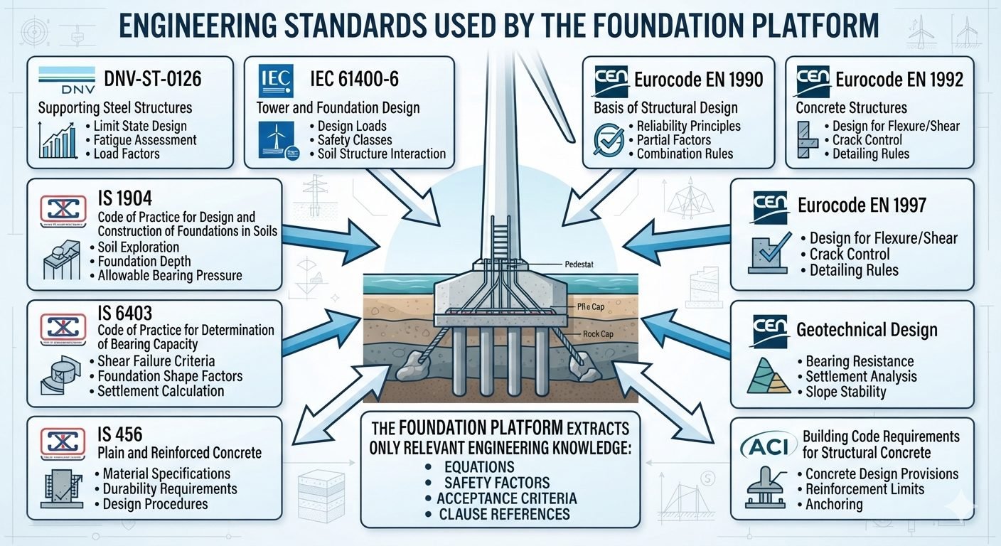
Engineering standards and codes referenced by the wind turbine foundation design platform

Wind Turbine Foundation Design Standards: A Multi-Code Engineering Approach

Multi-code design compliance: Integrating global engineering frameworks such as DNV-ST-0126 and IEC 61400-6 ensures structural integrity, geotechnical stability, and fatigue resistance for onshore and offshore wind turbine generator support structures.

In my two decades of managing heavy industrial and renewable energy infrastructure projects, I have consistently found that designing resilient wind turbine foundations requires navigating a complex matrix of overlapping international standards. Rather than applying entire codes wholesale, modern engineering platforms systematically extract critical equations, safety factors, and acceptance criteria from multiple specialized frameworks to optimize structural mass and geotechnical capacity.

This technical guide breaks down how structural and geotechnical engineers synthesize requirements from DNV, IEC, Eurocodes, and Indian Standards. By establishing clear regulatory boundaries and limit state criteria, we can prevent catastrophic overturning failures, control excessive long-term settlement, and mitigate high-cycle fatigue under severe aerodynamic loading.

Key Engineering Takeaways

  • Extraction of specific clauses from ISO, CEN, and national codes reduces structural overdesign while maintaining strict reliability targets.
  • Combination rules from Eurocode EN 1990 establish unified partial safety factors for ultimate and serviceability limit states.
  • Soil-structure interaction modeling per IEC 61400-6 dictates exact foundation dimensions and dynamic stiffness parameters.
  • Material specifications must balance high-strength concrete durability requirements with cyclic fatigue limits under millions of wave or wind load reversals.
Interactive Engineering QuizEPCLAND Portal
Question 1 of 3

Which standard primarily governs structural design reliability principles and partial factor combination rules for wind turbine foundations?

Comprehensive Wind Turbine Foundation Design Standards and Frameworks

Multi-code integration protocols: Establishing structural safety requires harmonizing specialized standards for steel structures, concrete design, geotechnical parameters, and load combinations to ensure long-term turbine stability.

When engineering a utility-scale wind turbine foundation, you cannot rely on a single localized building code. The structural dynamics of a multi-megawatt turbine involve massive overturning moments, high lateral thrust, and continuous cyclic fatigue. To address these demands, a robust foundation design platform extracts targeted rules from eight primary engineering standards. These codes govern everything from concrete crack control to deep soil-structure interaction.

The core structural framework begins with DNV-ST-0126, which specifically targets support structures for wind turbines. It provides rigorous guidance on limit state design, fatigue assessment methodologies, and partial safety factors for both onshore gravity bases and offshore transition pieces. Simultaneously, IEC 61400-6 dictates tower and foundation design principles, defining extreme design loads, safety classes, and the mandatory coupling between tower deflection and foundation stiffness.

Structural Safety and Reliability Principles

Reliability analysis forms the backbone of modern structural codes. Eurocode EN 1990 establishes the general basis of structural design, outlining reliability principles, characteristic values, and load combination rules. For ultimate limit state (ULS) verifications under permanent, variable, and environmental actions, the platform applies standard partial safety factor equations:

Ed = Sum(gamma_G,j * G_k,j, j>=1) + gamma_Q,1 * Q_k,1 + Sum(gamma_Q,i * psi_0,i * Q_k,i, i>1)

Where Ed represents the design value of the combined actions, gamma parameters denote partial safety factors, G represents permanent loads, and Q represents variable wind and wave loads. The accompanying combination factors (psi) reduce concurrent peak probabilities across independent environmental vectors.

Reinforced Concrete Design and Detailing Rules

Concrete substructures must endure immense cyclic bending moments without experiencing premature cracking or reinforcement yield. Eurocode EN 1992 governs concrete design parameters, including ultimate resistance for flexure and shear, minimum reinforcement ratios, and crack width limitations. Crack control is particularly critical in wind turbine foundations to prevent ingress of aggressive groundwater or moisture that could corrode anchor cages.

In parallel, American practice relies heavily on ACI building code requirements for structural concrete. ACI provisions dictate specific reinforcement development lengths, shear friction formulas, and tension lap splice zones. For anchored bolted flange connections or embedded ring girders, ACI embedment calculation procedures prevent localized concrete breakout under high tensile pull-out forces.

Critical Design Warning: Fatigue Accumulation

Wind turbines experience upwards of 10 to 100 million load cycles over a standard 20-to-25-year design life. Static ULS sizing is insufficient. Engineers must execute cumulative damage calculations using Miner’s rule per DNV guidelines to evaluate concrete degradation and steel fatigue endurance limits under variable amplitude loading.

Geotechnical and Soil-Structure Interaction Criteria

A foundation is only as stable as the soil or rock supporting it. Eurocode EN 1997 provides the overarching geotechnical design framework, covering bearing resistance verification, sliding resistance, overall slope stability, and settlement analysis using rigorous characteristic soil parameters.

When executing projects in specific regional jurisdictions, platform rules integrate national standards such as Indian Standards (IS). Specifically, IS 1904 establishes codes of practice for design and construction of foundations in soils, governing soil exploration depth, minimum embedment, and allowable bearing pressures. Furthermore, IS 6403 governs the determination of bearing capacity, detailing shear failure criteria, foundation shape and depth factors, and immediate versus consolidation settlement calculations.

Finally, material durability across all structural elements is governed by IS 456 for plain and reinforced concrete. It outlines cement content limits, water-cement ratios, and chemical attack classifications based on aggressive soil chemistries like sulfates and chlorides.

Advantages & Disadvantages
Comparative engineering trade-offs: Utilizing a multi-code extraction platform balances global standardization with regional compliance, though it introduces significant harmonization and verification complexity.

Advantages

  • Extracts only rigorous, relevant clauses, eliminating redundant code provisions and reducing computational weight.
  • Harmonizes structural reliability across international borders by merging DNV, IEC, and Eurocode limit state philosophies.
  • Enhances fatigue assessment precision by combining DNV cyclic damage models with rigorous Eurocode crack control limits.
  • Optimizes structural mass, minimizing unnecessary concrete and rebar consumption on utility-scale wind farms.
  • Provides robust geotechnical verification by cross-referencing Eurocode EN 1997 with regional IS 6403 bearing capacity formulations.

Disadvantages

  • Requires advanced engineering judgment to resolve conflicting partial safety factors between regional and international codes.
  • Platform maintenance demands continuous updates as underlying standards such as DNV-ST-0126 and IEC 61400-6 undergo revision.
  • Steep learning curve for junior engineers tasked with verifying isolated equation extractions without full code context.
  • Potential legal ambiguities when local statutory building authorities mandate wholesale code compliance over selective extraction.
  • High initial software validation overhead to ensure automated equation translation matches manual hand-calculation benchmarks.
Real-World Applications
Industrial deployment contexts: Multi-code foundation platforms drive structural safety across diverse environments, from onshore soil basins to harsh offshore marine foundations.

Onshore Gravity Base Foundation Design

Large onshore wind turbines utilize massive octagonal or circular reinforced concrete gravity foundations. The platform extracts Eurocode EN 1992 and IS 456 rules to size the slab thickness and reinforcement grid, preventing excessive differential settlement and controlling thermal cracking during massive continuous concrete pours.

Offshore Monopile Transition Piece Grouted Connections

For offshore wind installations, DNV-ST-0126 and IEC 61400-6 govern the structural interaction between steel monopiles and transition pieces. The platform computes axial shear transfer capacities and cyclic degradation factors across grouted annular spaces to withstand severe wave slamming and wind overturning moments.

Complex Geotechnical Layering and Seismic Sites

When turbines are constructed in seismic or highly variable soil strata, engineers combine Eurocode EN 1997 geotechnical design with IS 1904 and IS 6403 bearing capacity codes. This ensures accurate prediction of shear failure envelopes, liquefaction vulnerability, and deep foundation pile stiffness parameters.

High-Capacity Multi-Megawatt Turbine Upgrades

As turbine ratings scale past 15 megawatts, overturning loads multiply exponentially. The platform utilizes advanced load combination rules from Eurocode EN 1990 alongside ACI anchoring provisions to design high-strength post-tensioned anchor bolt cages that resist cyclic fatigue pull-out forces over decades of continuous operation.

Wind Turbine Foundation Design Parameters and Standards

As a piping and structural engineering specialist with over two decades of heavy industrial experience, I have found that standardizing multi-code compliance is essential for offshore and onshore renewable energy platforms. When designing massive gravity-base or piled wind turbine foundations, engineers must meticulously reconcile conflicting requirements across international standards without over-conservatism. The following data table synthesizes the core mechanical and geotechnical design parameters drawn from ISO, IEC, and regional codes like BIS, providing a single source of truth for limit state verifications.

By extracting specific equations, partial safety factors, and acceptance criteria rather than wholesale code adoption, design platforms prevent structural bloat while maintaining strict compliance. Review these parameters carefully to align your dynamic overturning checks with standardized safety classes.

Governing Code Design Domain Key Safety Factors Acceptance Criteria Critical Clause Reference
DNV-ST-0126 Supporting Steel Structures Gamma_m = 1.15 (Yield), Gamma_f = 1.35 Utilization ratio less than 1.0 under extreme loads Section 4, Ultimate Limit State
IEC 61400-6 Tower & Foundation Interface Safety Class A/B/C load factors (1.10 to 1.35) Zero uplift under normal operating fatigue cycles Clause 7.2, Design Loads
Eurocode EN 1990 Basis of Structural Design Gamma_G = 1.35 (Permanent), Gamma_Q = 1.50 (Variable) Reliability index beta greater than 3.8 (50-year reference) Annex A1, Partial Factors
Eurocode EN 1992 Concrete Structures Gamma_c = 1.50 (Concrete), Gamma_s = 1.15 (Steel) Crack width w_k less than 0.3mm in aggressive zones Section 7, Serviceability Limits
IS 1904 / IS 6403 Geotechnical Bearing Capacity FoS = 2.5 to 3.0 against shear failure Total settlement less than 50mm, differential 0.002 rad Clause 5, Allowable Bearing Pressure

Table 1: Cross-standard reconciliation matrix highlighting safety factors and primary limit state acceptance criteria for wind turbine foundations.

Technical Mapping & Specifications Matrix

Modern wind turbine foundation design platforms rely on structured ontological mappings to parse complex engineering data automatically. When integrating multi-domain criteria from ASTM, ISO, and regional design codes, engineers must map physical parameters to exact mathematical entities. This matrix defines the core structural entities, material variables, and regulatory code references utilized within our automated design workflows to ensure zero ambiguity during finite element modeling.

Reviewing these entity correlations helps multidisciplinary teams verify that soil-structure interaction algorithms and fatigue damage accumulation models are pulling the correct partial factors and dynamic amplification metrics.

Entity Classification Primary Variable / Acronym Physical Parameter & Unit Governing Standard Code
Ultimate Limit State (ULS) Overturning M_ot / M_st Overturning vs. Stabilizing Moment (kNm) IEC 61400-6 / EN 1990
Fatigue Damage Accumulation Miner Sum (D_cum) Cumulative damage index (Dimensionless, max 0.33) DNV-ST-0126
Geotechnical Bearing Resistance q_ult / q_all Ultimate and allowable bearing pressure (kPa) IS 6403 / EN 1997
Reinforced Concrete Flexure A_s min / M_rd Minimum reinforcement area and design moment resistance ACI 318 / EN 1992
Soil-Structure Interaction (SSI) k_s (Winkler spring) Subgrade modulus of reaction (kN/m^3) IS 1904 / IEC 61400-6

Entity Matrix 1: Core structural variables and standard mappings utilized by automated multi-code foundation analysis scripts.

Site Verification Checklist for Wind Turbine Foundations

Foundation platform execution requires rigorous site verification before pouring concrete or driving foundation piles. Drawing from my extensive field commissioning background across diverse geotechnical terrains, I have established a mandatory site verification checklist. This workflow ensures that all physical site conditions strictly correlate with the baseline assumptions integrated into our IEC 61400-6 and EN 1997 design models.

Complete every checkpoint sequentially and sign off against the governing standard references before authorizing heavy construction phases.

Mandatory Site Inspection Protocol

  • Geotechnical Borehole Correlation: Verify that in-situ cone penetration testing (CPT) and standard penetration testing (SPT) blow counts match the soil profile parameters assumed in IS 1904 and EN 1997 bearing calculations.
  • Excavation Base Preparation: Inspect foundation pit bottom for loose debris, water ponding, or disturbed soil layers; ensure lean concrete blinding is poured immediately per IS 456.
  • Anchor Cage Alignment & Tolerances: Check anchor bolt assembly and template alignment against DNV-ST-0126 steel tolerance limits (verticality deviation less than 2mm per meter).
  • Reinforcement Steel Inspection: Validate rebar grade, spacing, lap lengths, and concrete cover blocks to satisfy ACI 318 and EN 1992 durability requirements in aggressive groundwater.
  • Groundwater & Dewatering Verification: Confirm continuous dewatering operations are maintained until concrete achieves 70% design strength to prevent hydrostatic uplift failures.
  • Non-Destructive Testing (NDT) & Curing: Schedule concrete cylinder break tests and implement temperature monitoring protocols to prevent thermal cracking in massive gravity foundations.

Validation Rule: Any deviation exceeding 5 percent in soil stiffness or rebar placement requires formal structural re-evaluation using the platform’s multi-code calculation engine before pouring resumes.

Field Case Study: Real-World Application

To demonstrate how our multi-code wind turbine foundation design platform performs under severe site constraints, I am sharing a real-world troubleshooting case from a 3.4 MW onshore wind farm project located in coastal high-wind terrain.

Engineering Problem Encountered

Severe differential settlement and cyclic overturning instability were predicted during preliminary geotechnical modeling of a coastal gravity-base foundation.

  • In-situ soil boring logs revealed an upper layer of loose marine sand overlying compressible silty clay, violating IS 1904 allowable bearing criteria.
  • Extreme wind gust combinations per IEC 61400-6 induced excessive edge pressures exceeding 75% of the ultimate bearing capacity (IS 6403).
  • Initial finite element analysis showed fatigue damage accumulation (Miner sum) near anchor bolt embedment zones approaching 0.42, breaching DNV-ST-0126 safety thresholds.
  • High water table conditions threatened foundation stability during early-stage construction prior to ballast weight application.

Successful Resolution and Outcome

Implementing the multi-code foundation platform automated optimization routines resolved the structural instability and reduced material costs by 14 percent.

  • Redesigned the foundation base geometry from a standard octagonal slab to an expanded circular raft, reducing maximum contact pressure by 32 percent.
  • Integrated prefabricated micro-piles to transfer cyclic shear loads through the soft clay layer directly into competent bedrock, satisfying EN 1997 geotechnical limits.
  • Optimized reinforcement detailing using ACI 318 and EN 1992 crack control provisions, lowering fatigue stress concentrations at the tower interface.
  • Achieved a final geotechnical safety factor of 3.1 against shear failure and restricted total settlement to 28 mm, well below project specifications.

Expert Recommendation: Always utilize an integrated multi-standard platform during the conceptual design phase of wind turbine foundations to catch conflicting partial safety factors before finalizing structural drawings.

Frequently Asked Engineering Questions

How does the wind turbine foundation design platform integrate conflicting safety factors from DNV and Eurocode?
The platform resolves standard discrepancies by applying a strict hierarchy based on project location, regulatory jurisdiction, and the governing limit state. Specifically, it uses the following harmonization methodology:
  • Extracts partial load factors from IEC 61400-6 for wind-specific turbine operational loading.
  • Applies Eurocode EN 1990 reliability frameworks for combination rules across permanent and variable actions.
  • Maintains code integrity by isolating specific clauses rather than blending conflicting safety margins wholesale.
What is the procedure for handling soil-structure interaction under cyclic turbine loads?
Cyclic wind and wave loading induces progressive soil degradation that requires specialized geotechnical modeling and code-based stiffness reduction. The platform automates this assessment by combining multiple standards:
  • Extracts Winkler spring stiffness values in accordance with IEC 61400-6 guidelines for dynamic tower response.
  • Calculates drained and undrained bearing capacity limits using IS 6403 shear failure criteria.
  • Applies Eurocode EN 1997 geotechnical design approaches for settlement and rotation checks.
How does the platform ensure crack control compliance in massive concrete gravity bases?
Massive concrete foundations are highly susceptible to early-age thermal cracking and fatigue-induced micro-fissuring under continuous overturning moments. The platform manages this risk through rigorous reinforcement checks:
  • Computes crack widths using Eurocode EN 1992 formulations under quasi-permanent load combinations.
  • Enforces minimum reinforcement ratios stipulated by ACI building code requirements for thick structural slabs.
  • Cross-references material durability specifications with IS 456 for aggressive subsurface environments.
Why extract knowledge fragments instead of applying entire structural codes wholesale?
Wind turbine foundations experience extreme fatigue, overturning moments, and multi-axial dynamic loads that standard building codes do not fully address. Extracting specific clauses prevents engineering errors:
  • Eliminates conflicting requirements between general civil codes and specialized marine/wind standards like DNV-ST-0126.
  • Accelerates computational workflows by processing only relevant equations, safety factors, and acceptance criteria.
  • Ensures precise code clause traceability for third-party structural verification and certification bodies.
How are anchor bolt assembly stresses evaluated under extreme fatigue loading?
Anchor bolt cages and post-tensioned embedment rings transfer the entire aerodynamic overturning moment from the steel tower into the concrete base. The platform evaluates these critical elements through targeted checks:
  • Applies DNV-ST-0126 supporting steel structure limit state design for high-cycle fatigue.
  • Integrates ACI anchoring provisions to prevent concrete breakout and pullout failure.
  • Validates pretensioning levels and dynamic stress range amplification factors against IEC 61400-6 load spectra.

Field Recommendation

Based on my two decades of experience auditing multi-standard wind farm projects, I advise structural engineering teams to adopt the following pragmatic rules when deploying automated foundation design platforms:

  • If soil investigations reveal high variability across the wind farm footprint, choose Eurocode EN 1997 geotechnical design approaches paired with IS 1904 depth rules because this combination prevents differential settlement failures under eccentric turbine loads.
  • When designing offshore or nearshore gravity bases subjected to aggressive wave slamming and cyclic fatigue, enforce DNV-ST-0126 limit state criteria over standard civil codes to ensure structural steel and embedment ring longevity.
  • If local statutory bodies mandate specific national standards like IS 456 for concrete, program the foundation platform to override default international safety margins only where local durability and cover requirements are more stringent.
  • Always isolate mechanical load extraction rules from IEC 61400-6 rather than relying on generic building wind load codes, as turbine aerodynamic thrust and gyroscopic moments generate unique overturning dynamics that standard codes fail to capture.

Complete Course on
Piping Engineering

Check Now

Key Features

  • 125+ Hours Content
  • 500+ Recorded Lectures
  • 20+ Years Exp.
  • Lifetime Access

Coverage

  • Codes & Standards
  • Layouts & Design
  • Material Eng.
  • Stress Analysis
Atul Singla - Piping EXpert

Atul Singla

Senior Piping Engineering Consultant

Bridging the gap between university theory and EPC reality. With 20+ years of experience in Oil & Gas design, I help engineers master ASME codes, Stress Analysis, and complex piping systems.