Wind Turbine Foundation Design Platform Architecture
In my two decades of industrial structural and piping engineering practice, I have witnessed how multi-megawatt wind turbine installations push foundation design to its absolute limits. Rotor-nacelle assemblies generate massive overturning moments, relentless cyclic thrust, and complex shear forces that transfer directly through the pedestal into the subsurface strata. To conquer these challenges safely, modern engineering relies on a unified wind turbine foundation design platform that couples geotechnical mechanics with rigorous structural analysis.
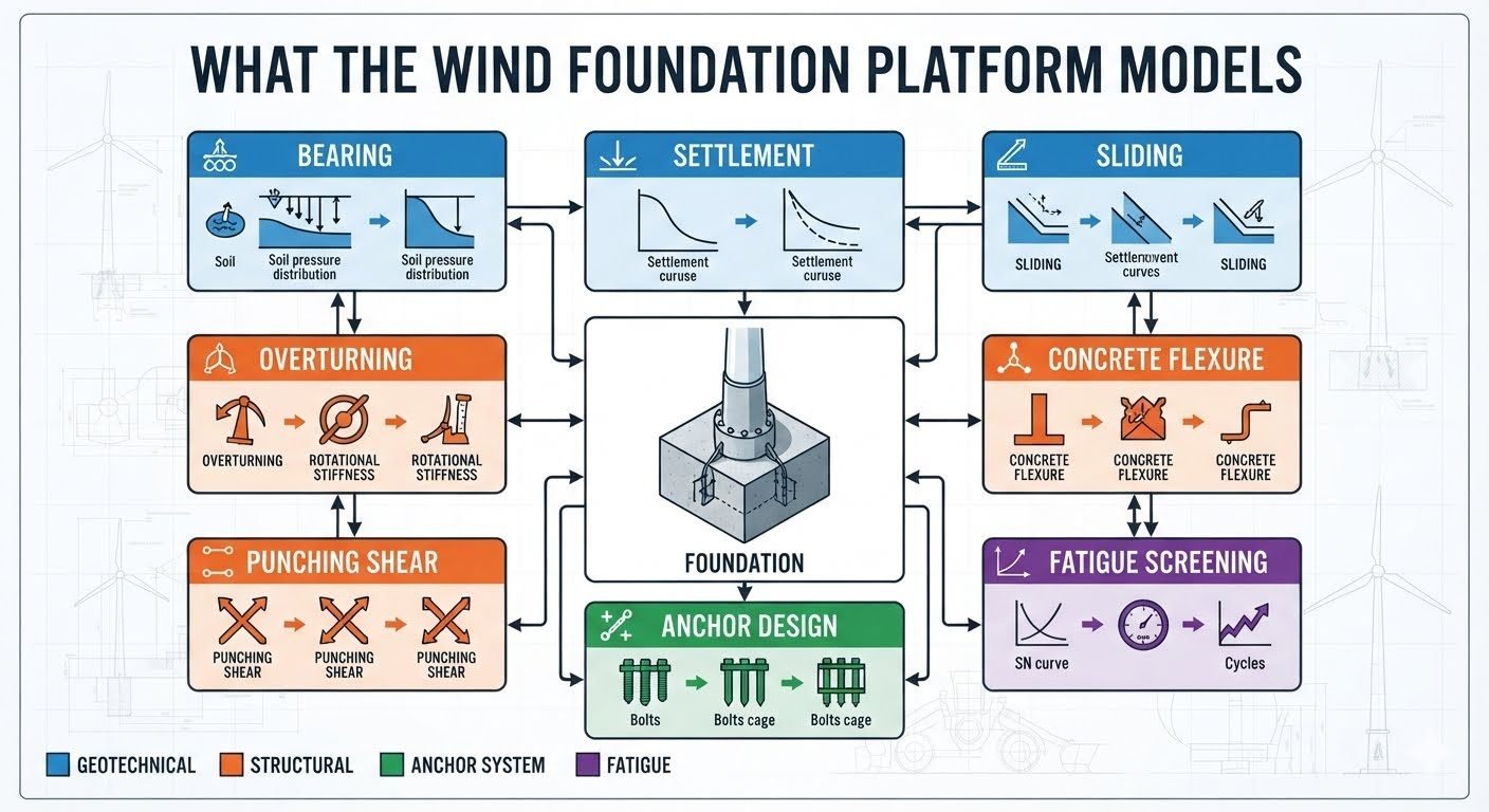
Evaluating these multi-axial forces requires moving beyond isolated spreadsheet checks toward an integrated modeling ecosystem. By synthesizing nine specialized modules around a central foundation model, engineers can simulate realistic soil-structure interaction, concrete stress distribution, and fatigue degradation over a twenty-year operational lifespan. Let us examine how this architecture governs safe and reliable wind energy infrastructure.
Key Engineering Takeaways
- Central foundation models synchronize nine distinct geotechnical, structural, and fatigue analysis modules.
- Geotechnical modules govern bearing capacity, settlement trajectories, and lateral sliding resistance.
- Structural modules verify overturning stability, concrete flexural strength, and punching shear resistance.
- Anchor systems and fatigue screening protect against bolt pull-out and cumulative cyclic degradation.
Wind Turbine Foundation Design Analysis Architecture
Designing a gravity-base or piled wind turbine foundation demands rigorous coordination across four distinct engineering disciplines. At the heart of the platform sits a centralized parametric model that feeds geometry, material properties, and environmental loads into nine specialized computational modules. This decoupled yet synchronized approach ensures that changes in base diameter or pedestal thickness instantly update soil pressure profiles and reinforcement stress ratios.
The geotechnical discipline forms the foundation’s physical interface with the earth, encompassing bearing, settlement, and sliding analysis. Bearing analysis evaluates soil pressure distribution beneath the circular or octagonal mudmat, comparing maximum contact stress against allowable bearing capacity governed by ASTM D1587 soil parameters. Settlement analysis models immediate elastic consolidation alongside time-dependent secondary creep curves, ensuring differential settlement remains within rigid turbine tilt tolerances. Sliding analysis cross-references lateral wind shear against friction coefficients at the concrete-soil interface, factoring in mobilized earth passive pressure along the vertical foundation flanks.
Transitioning upward, the structural discipline addresses the superstructure-to-foundation load path through overturning, concrete flexure, and punching shear modules. Overturning analysis examines rotational stiffness and contact area loss, verifying that the resultant load vector remains within the middle third kernel under extreme gust conditions. Concrete flexure analysis calculates internal bending moments across critical radial sections, sizing tension and compression reinforcement in accordance with ACI 318 building code requirements. Punching shear analysis evaluates two-way shear stresses around the cylindrical pedestal, preventing catastrophic cone failure under concentrated vertical and moment transfers.
Core Analytical Workflow Parameters
- Bearing Capacity Factor: Evaluates ultimate bearing pressure using Terzaghi and Meyerhof formulations adjusted for eccentric inclined loads.
- Rotational Stiffness: Quantifies foundation rocking stiffness to prevent dynamic frequency coupling with tower natural frequencies.
- Punching Perimeter: Analyzes critical shear perimeters located at 0.5 times effective slab depth away from the pedestal face.
- Cyclic Stress Ratio: Quantifies stress range variations in anchor bolts to prevent high-cycle fatigue failure.
The final two disciplines—anchor system and fatigue screening—safeguard the longevity of the assembly against dynamic degradation. Anchor design analysis checks pretensioned bolt cages, embedment lengths, and concrete breakout cone capacities under combined tensile and shear reversals. Simultaneously, fatigue screening utilizes rainflow counting algorithms on historical wind time-series data to plot cumulative damage indices against S-N curves. This comprehensive framework guarantees compliance with international wind turbine standards throughout a twenty-year operational envelope.
Critical Engineering Warning: Geotechnical Uplift
Failure to account for partial base uplift during extreme 50-year wind gusts can result in progressive soil erosion beneath the mat. Ensure that geotechnical sliding and overturning modules incorporate eccentric load reductions and buoyancy corrections for high water table sites.
Platform Advantages
- Seamless data transfer between geotechnical settlement models and structural concrete reinforcement engines.
- Automated cyclic fatigue screening reduces manual calculation errors for multi-megawatt turbine setups.
- Centralized parametric updates eliminate discrepancies between foundation geometry and soil pressure assumptions.
- Full compliance verification against international structural codes like ACI 318 and IEC 61400.
- Enhanced visualization of stress concentrations around anchor bolt cages and pedestal interfaces.
Platform Disadvantages
- Steep learning curve required for engineers mastering nine distinct geotechnical and structural modules.
- High computational resource demand when running full time-series fatigue and finite element mesh iterations.
- Sensitivity to input parameter accuracy, where poor soil investigation data propagates severe sizing errors.
- Substantial licensing and maintenance overhead for specialized multi-physics structural software suites.
- Potential over-conservatism in automated punching shear algorithms requiring manual engineering override.
Onshore Multi-Megawatt Wind Farms
Onshore utility-scale wind farms utilize gravity-base pads subjected to intense directional shear and overturning moments from large 5.0 MW turbines. The platform coordinates bearing and settlement modules to prevent excessive differential tilt on variable glacial till soils. Simultaneously, concrete flexure and anchor design modules size the massive octagonal reinforcement cages efficiently.
Offshore Monopile Transition Pieces
Offshore transition pieces and jacket transition platforms rely heavily on fatigue screening and punching shear modules. The dynamic wave-wind slamming interaction induces high-cycle stress reversals that require rigorous S-N curve evaluation. The platform models grouted connection stresses and bolt cage integrity under severe marine environmental loading.
Complex Mountainous Terrain Installations
Ridge-line wind installations frequently encounter sloping bedrock and asymmetrical soil profiles across the foundation footprint. Sliding and overturning analysis modules evaluate asymmetric lateral soil resistance and micro-piled rock anchors. This ensures slope stability and prevents catastrophic foundation sliding on high-grade elevation gradients.
Repowering and Upgraded Turbine Retrofits
Repowering projects involve mounting heavier, taller turbine nacelles onto existing legacy foundation footprints. Engineers employ the platform’s central foundation model to re-verify concrete flexure and fatigue limits under increased thrust loads. This determines whether existing gravity mats can be retained or require structural strengthening.
Wind Turbine Foundation Analysis Parameters and Governing Design Standards
Evaluating wind turbine foundation design platform metrics requires strict alignment with recognized international codes and standards. In my engineering practice, establishing rigorous baseline parameters for geotechnical capacities and structural section resistance prevents premature failure modes during extreme meteorological events. The following engineering data table outlines the core parameters, design equations, governing standards, and performance thresholds utilized across the nine interconnected analysis modules.
Each parameter within this matrix directly correlates with the four core engineering disciplines managed by the platform. Geotechnical stability relies heavily on allowable bearing pressures and shear resistance coefficients, whereas structural integrity demands exact adherence to ASCE and ACI provisions. Review these threshold values carefully to ensure your finite element modeling inputs match field-verified geotechnical reports.
| Analysis Module | Core Governing Parameter | Primary Code Reference | Acceptance Threshold |
|---|---|---|---|
| Bearing Analysis | Ultimate Soil Pressure (q_ult) | ASCE 7 / ISO 19901 | Pressure <= q_allowable (FS >= 3.0) |
| Settlement Analysis | Immediate & Consolidation (S_t) | ASTM D2435 | Total < 50mm, Differential < 0.002 rad |
| Sliding Analysis | Lateral Resistance (R_sliding) | ASCE/SEI 48 | FS >= 1.5 under factored loads |
| Overturning Analysis | Eccentricity Ratio (e = M/V) | DNVGL-ST-0126 | Core of base maintained (e < B/6) |
| Concrete Flexure Analysis | Bending Moment (M_u vs phi M_n) | ACI 318 | M_u <= phi M_n (phi = 0.90) |
| Punching Shear Analysis | Critical Perimeter Shear (V_u) | ACI 318 Chapter 22 | V_u <= phi V_c (phi = 0.75) |
| Anchor Design Analysis | Tensile Stress & Bond Capacity | AISC Design Guide 1 | Steel stress < 0.90 Yield |
| Fatigue Screening Analysis | Cumulative Damage Index (Miner) | DNVGL-RP-C203 | Damage Sum D < 0.50 |
Note: All safety factors listed above assume standard drained soil conditions and normal operational load combinations as defined in international wind energy guidelines.
Technical Mapping & Specifications Matrix
Advanced computational platforms require structured data taxonomies to map physical components to software analysis nodes. In wind turbine foundation design platform architecture, every physical entity—ranging from the high-strength anchor bolt cage to the mass concrete mat—is represented by specific mathematical models and software entities. This entity matrix establishes the clear nomenclature and technological relationships utilized in our multi-module design framework.
By standardizing these data entities, the platform ensures seamless data exchange between the geotechnical soil-spring generators and the finite element structural mesh. Review the mapping below to understand how structural components, material grades, and analytical subroutines interconnect to verify long-term structural integrity.
| Structural Entity | Platform Module Class | Material / Parameter Standard | Analytical Output Metric |
|---|---|---|---|
| Mat Foundation Slab | Structural & Geotechnical Core | ASTM C150 (Type V Cement) | Bending moments, crack widths |
| Pedestal / Tower Ring | Overturning & Flexure | ACI 318 High-Strength Mix | Contact stress distribution |
| Anchor Bolt Cage | Anchor Design Module | ASTM A615 / A706 Grade 75 | Tensile force, pullout capacity |
| Soil Subgrade Interface | Bearing & Settlement | ASTM D1194 (Plate Bearing) | Winkler modulus (k_s) |
| Reinforcing Steel Mesh | Concrete Flexure & Shear | ASTM A615 Grade 60 | Stress ranges, fatigue damage |
System Integration Note: Entity definitions feed directly into the automated calculation pipeline, validating structural safety factors against extreme gust scenarios.
Site Verification Checklist for Foundation Platform Deployment
Deploying a wind turbine foundation design platform requires rigorous site-specific verification to ensure computational models reflect true geological and environmental conditions. In my project engineering assignments, overlooking minor soil parameter deviations or bolt cage installation tolerances has repeatedly led to costly remedial interventions. This checklist provides a systematic protocol for validating field data before locking in platform design calculations.
Use this structured framework to verify geotechnical investigation reports, structural reinforcement drawings, and anchor assembly installations against governing international codes such as ASCE and ACI. Every checkpoint must be formally signed off by the lead geotechnical and structural engineers of record.
Pre-Design Geotechnical Verification
- Borehole Data Completeness: Confirm soil borings extend at least 1.5 times the foundation width below subgrade level to capture consolidation strata.
- Groundwater Table Monitoring: Verify seasonal high water table levels and hydrostatic uplift pressures are incorporated into buoyancy and sliding models.
- Dynamic Soil Parameters: Ensure shear wave velocity (Vs30) and cyclic triaxial test results are loaded into the fatigue screening module.
Structural and Anchor Assembly Inspection
- Bolt Cage Alignment Tolerances: Inspect template jig positioning to ensure anchor bolt verticality and radial placement meet AISC specifications.
- Reinforcement Cover Verification: Check bottom and top mat concrete cover blocks to guarantee compliance with ACI 318 environmental exposure categories.
- Thermal Control Monitoring: Install thermocouple arrays in mass concrete pours to manage core-to-surface temperature differentials and prevent thermal cracking.
Platform Computational Sign-Off
- Load Combination Audit: Cross-check platform-generated wind turbine operating and extreme storm load cases against OEM nacelle reaction matrices.
- Fatigue Spectrum Validation: Confirm S-N curve damage accumulation calculations align with 25-year operational design life requirements.
Verification Mandate: Completion of every checklist item is legally required before pouring mass concrete or installing turbine tower sections.
Field Case Study: Real-World Application
Practical implementation of multi-module foundation platforms often encounters unexpected site complexities that test initial engineering assumptions. During the construction of a 3.4 MW wind farm on complex coastal terrain, our engineering team utilized the platform to evaluate marginal bearing strata and severe lateral wind overturning moments. The following case study details the specific geotechnical challenges encountered and the corrective measures deployed.
Engineering Problem: Differential Settlement and Overturning Risk
Initial geotechnical investigations revealed highly variable limestone-weathered clay strata across the turbine pad footprint, threatening excessive differential settlement and foundation base uplift under severe typhoons.
- Soil borings indicated localized soft pockets with allowable bearing pressures dropping below 150 kPa.
- Preliminary platform runs for overturning analysis showed base eccentricity exceeding the middle-third core limit under 50-year gust loads.
- Sliding stability factors of safety fell below the mandatory 1.5 threshold due to low clay-concrete friction coefficients.
- Anchor cage tensile stress concentrations approached 85 percent of yield during cyclic fatigue screening runs.
Engineering Outcome: Optimized Multi-Module Remediation
By re-running the interconnected analysis modules with modified subgrade spring stiffness and enlarged gravity base geometry, the engineering team successfully stabilized the turbine foundations without compromising construction schedules.
- Foundation mat diameter was increased by 1.2 meters, restoring base eccentricity safely within the middle-third core (e < B/6).
- Geotechnical settlement modeling verified total long-term settlement remained below 35 mm, well within allowable OEM operational limits.
- Shear keys integrated into the base slab increased sliding resistance, raising the factor of safety to 1.82.
- Fatigue screening confirmed cumulative damage index remained under 0.40 across the 25-year design life.
Recommendation: Always couple automated platform design iterations with physical site quality control to ensure geotechnical parameters match structural assumptions.
Frequently Asked Engineering Questions
How does bearing analysis integrate settlement curves for wind turbine foundations?
- High eccentric edge pressures trigger localized plastic yield beneath the mudmat.
- Cyclic wind moments alter contact stress profiles, accelerating primary settlement rates.
- Finite element platforms couple soil modulus degradation directly with accumulated micro-strains.
What role does sliding resistance play under severe lateral wind loading?
- Frictional resistance degrades dynamically as cyclic horizontal shear induces progressive soil shear strain.
- Base interface roughness and drainage layers dictate the ultimate friction coefficient.
- Skirt walls or shear keys are introduced when self-weight friction proves insufficient alone.
Why is overturning behavior coupled with rotational stiffness calculations?
- Loss of effective contact area softens the foundation subgrade reaction modulus.
- Tower eigenfrequency shifts can cause dangerous resonance with turbine blade passing frequencies.
- Nonlinear rotational spring models capture uplift separation at the soil-concrete interface.
How do concrete flexure and punching shear interact under concentrated loads?
- High bending moments require dense bottom and top orthogonal reinforcing mats.
- Punching shear perimeters demand closed stirrups or shear stud rails near the pedestal.
- Combined shear-flexure interaction curves dictate minimum pedestal and slab thickness dimensions.
What methodology drives fatigue screening for anchor bolt cages and S-N curves?
- Rainflow counting algorithms decompose variable amplitude stress histories into discrete cycles.
- Preload levels in anchor bolts must exceed operational cyclic stress ranges to prevent fatigue cracking.
- Weld details and thread notch sensitivity dictate the applicable fatigue class category.
Field Recommendation
- If site geotechnical investigations reveal soft or variable clay strata, choose deep caisson or pile-supported foundation variants over gravity mats because differential settlement will otherwise violate strict turbine tilt tolerances.
- When designing the anchor bolt cage for multi-megawatt turbines, specify high-strength preloaded post-tensioned assemblies with corrosion-resistant grouting to withstand extreme cyclic fatigue without losing bolt tension.
- Always couple finite element soil-structure interaction models with dynamic wind turbine aeroelastic software rather than relying on static bearing pressure assumptions, ensuring accurate natural frequency calculations.
- In seismic-prone or high-wind coastal regions, mandate the inclusion of perimeter shear keys and increased base slab thickness to satisfy sliding resistance safety factors under combined lateral-overturning loads.
Complete Course on
Piping Engineering
Check Now
Key Features
- 125+ Hours Content
- 500+ Recorded Lectures
- 20+ Years Exp.
- Lifetime Access
Coverage
- Codes & Standards
- Layouts & Design
- Material Eng.
- Stress Analysis
