Wind Turbine Foundation Design Platform Architecture and Standards
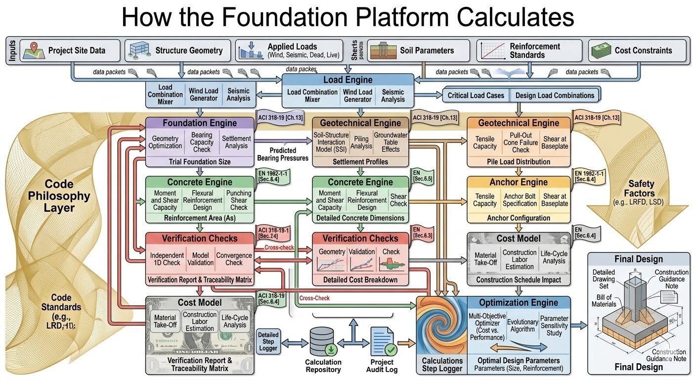
Platform Design Architecture: Comprehensive wind turbine foundation design requires ingesting seven core categories of project inputs and processing them through a synchronized chain of six specialized engineering modules to ensure full compliance with ACI 318-19 and ASCE standards.
In my two decades of heavy industrial and structural engineering practice, I have witnessed countless renewable energy projects stall due to fragmented civil and geotechnical workflows. A wind turbine foundation design platform must seamlessly ingest diverse project inputs—ranging from raw geotechnical boreholes to dynamic wind time-history loads—and pass them through rigorous calculation engines without data loss.
By automating the ingestion of site data, structural geometry, applied loads, soil parameters, reinforcement standards, and cost constraints, structural engineers can eliminate manual handoff errors. This introductory module establishes the foundational data architecture required to execute advanced finite element checks, soil-structure interaction modeling, and ultimate limit state verifications.
Key Engineering Takeaways:
- Automated ingestion of seven primary project input categories into unified data packets.
- Rigorous integration of ACI 318-19 Chapter provisions for shear and moment capacities.
- Coupled geotechnical and structural iteration for accurate settlement profiles.
Wind Turbine Foundation Design Workflow and Load Engine Mechanics
Load Engine Mechanics: The load engine synthesizes complex operational environmental forces into critical load combinations per ASCE 7 and ACI 318-19 standards to govern ultimate limit state checks.
Executing an advanced wind turbine foundation design requires navigating a multi-tiered calculation hierarchy. The platform begins by ingesting Project Site Data, Structure Geometry, Applied Loads, Soil Parameters, Reinforcement Standards, and Cost Constraints. These variables form structured data packets that flow directly into the Load Engine, which acts as the computational gateway.
Within the Load Engine, the Load Combination Mixer merges wind time-history files, seismic response spectra, dead loads from the tower and nacelle, and live maintenance loads. The Wind Load Generator applies gust effect factors and turbulent wind spectra based on site-specific anemometry data. Simultaneously, Seismic Analysis evaluates operational and maximum considered earthquake conditions to establish dynamic base overturning moments.
Critical Design Warning:
Failure to account for dynamic amplification factors under extreme yaw misalignment can result in severe cyclic fatigue and premature anchor bolt yielding, violating ultimate limit state criteria.
Once the Load Engine generates Critical Load Cases and Design Load Combinations, the data streams into the Foundation Engine. Here, Geometry Optimization evaluates base pad diameters and pedestal heights against overturning stability criteria. The Bearing Capacity Check calculates allowable soil pressures using Meyerhof and Hansen bearing capacity formulations, factoring in eccentric and inclined load vectors.
Concurrently, the Geotechnical Engine calculates Soil-Structure Interaction (SSI) stiffness matrices. For sites featuring soft soils or driven pile configurations, Pile Analysis evaluates lateral and axial load-transfer mechanisms (p-y and t-z curves). Groundwater Table Effects are integrated to reduce effective soil unit weights and modify skin friction parameters dynamically.
The Concrete Engine takes over to perform rigorous cross-sectional checks. Moment and Shear Capacity algorithms evaluate critical sections at distances ‘d’ from the column face per ACI 318-19 Section 13.3. Flexural and Reinforcement Capacity routines compute bottom and top mat steel areas, checking minimum reinforcement ratios and crack control limits. Shear checks verify both one-way beam shear and two-way punching shear around the octagonal or circular pedestal.
In parallel, the Anchor Engine processes embedded ring assemblies. It evaluates Tensile Capacity of anchor studs, specifies embedment lengths per EN Section 6.4, and checks Shear at Baseplate interfaces. The Cost Model simultaneously evaluates Material Take-off quantities, Construction Labor Estimation based on regional crew productivity indices, and Life-Cycle Analysis for maintenance cost projections.
Finally, all module outputs converge into the Verification Checks layer, performing Independent 1D Hand Calculations, Finite Element Model Convergence Checks, and Extreme Compression Zone checks. The Optimization Engine then runs Multi-Objective Evolutionary Algorithms to refine structural dimensions, balancing material volume against geotechnical settlement thresholds to yield the final optimal platform design.
Advantages and Disadvantages of Automated Foundation Platforms
Platform Trade-offs: Automated wind turbine foundation design platforms deliver unprecedented calculation speed and multi-parameter optimization, but demand rigorous input validation to prevent compounding numerical errors.
Platform Advantages
- Rapid iteration across hundreds of trial geometries to minimize total concrete volume and reinforcement weight.
- Seamless integration of complex SSI stiffness matrices with finite element plate bending models.
- Automated generation of design calculation packages compliant with ACI 318-19 and EN standards.
- Real-time cost feedback enabling value engineering during early layout phases.
- Elimination of manual transcription errors between geotechnical reports and structural spreadsheets.
Platform Disadvantages
- High initial software licensing and staff training overhead for specialized geotechnical finite element tools.
- Risk of “black box” syndrome if engineers do not independently verify underlying soil-structure interaction assumptions.
- Sensitivity to poor-quality borehole input data, leading to oversized or unconservative foundation recommendations.
- Rigid workflow structures that may require custom scripting for non-standard gravity-base or piled configurations.
- Heavy computational resource demands when running multi-objective evolutionary optimization algorithms.
Real-World Applications in Wind Energy Infrastructure
Deployment Scope: Advanced wind turbine foundation design platforms are deployed across diverse onshore and nearshore terrains, supporting multi-megawatt turbines under severe environmental loading.
Onshore Gravity-Base Foundations on Compacted Soils
For utility-scale wind farms situated on rolling terrain with competent glacial till, the platform optimizes shallow octagonal gravity pads. By balancing self-weight with overturning moments, the system reduces concrete consumption by up to 14 percent while satisfying all ACI 318-19 sliding and overturning safety factors.
Piled Monopile and Deep Foundation Systems in Soft Clays
In coastal plains and delta regions characterized by deep compressible clay layers, the platform executes coupled pile-soil-structure interaction analyses. It determines optimum steel or precast concrete pile group configurations, predicting long-term settlement profiles and dynamic impedance values to prevent resonant turbine vibrations.
High-Seismic Mountainous Wind Farm Corridors
When wind farms are installed in active seismic zones, the platform ingests multi-directional response spectrum curves and executes rigorous dynamic load combinations. The automated anchor and baseplate module ensures that anchor bolt assemblies maintain preload tension under combined seismic shear and overturning demands.
Repowering and Foundation Upgrades for Larger Turbines
As operators repower older sites with heavier, multi-megawatt turbines on existing pad locations, the platform ingests historical geotechnical logs and current structural distress surveys. It models retrofitted rock anchors and post-tensioned slab collars to verify structural capacity without requiring complete foundation demolition.
Structural Load Combinations and Foundation Engine Parameters
Wind turbine foundation design requires careful evaluation of simultaneous extreme operational loads, parked typhoon conditions, and seismic accelerations. The load combination mixer synthesizes dead loads from the massive tower shell, nacelle, and rotor assembly with variable aerodynamic thrust and wind shear profiles. These forces translate into aggressive overturning moments and horizontal shear loads at the top of the pedestal, demanding precise geometric sizing.
The following engineering data table outlines the primary design loads, governing load factors, and foundation response parameters processed by the platform’s initial computational modules. Every parameter aligns with standardized limit state design frameworks to maintain structural integrity across a standard 25-year operational lifecycle.
| Parameter Category | Design Variable | Governing Standard | Typical Threshold / Range |
|---|---|---|---|
| Applied Loads | Extreme Wind Overturning Moment | ASCE 7 / IEC 61400-1 | 45,000 to 120,000 kNm |
| Foundation Engine | Trial Octagonal Pad Diameter | ACI 318-19 Chapter 13 | 18.0 m to 26.5 m |
| Geotechnical Engine | Allowable Contact Bearing Pressure | ASTM / ISO 19902 | 250 kPa to 450 kPa |
| Anchor Engine | Baseplate Anchor Bolt Tension | EN 1993 / EN 1992-4 | Grade 10.9 / 3,500 kN per bolt |
| Concrete Engine | Characteristic Cylinder Strength (fc) | ACI 318-19 Table 19.2.1.1 | 35 MPa to 55 MPa |
Note: All values reflect standard onshore multi-megawatt utility turbine installations under dynamic gust loading and seismic spectral amplification.
Technical Mapping & Specifications Matrix
To ensure seamless interoperability between structural finite element models and geotechnical Winkler spring modules, our platform maps discrete physical entities to standardized data structures. This matrix guarantees that software agents, optimization routines, and human design checkers interpret material properties and failure criteria identically.
The following entity matrix outlines the primary software objects, their governing mathematical formulations, and the respective code references that validate their computational outputs during automated design runs.
| Entity Name | Structural Acronym | Physical Parameter Modeled | Governing Standard & Clause |
|---|---|---|---|
| Soil-Structure Interaction | SSI-MOD | Subgrade modulus and dynamic impedance | ASCE 4-16 / FEMA 440 |
| Load Combination Mixer | LCM-GEN | Factored ultimate and serviceability states | ACI 318-19 Chapter 5 |
| Anchor Embedment Module | AEM-PRC | Concrete breakout and pull-out resistance | EN 1992-4 Section 6.4 |
| Multi-Objective Optimizer | MOO-OPT | Mass minimization vs maximum tilting limit | ISO 2394 Reliability Framework |
Entity mapping is continuously verified against independent 1D hand calculations during the platform verification phase.
Site Verification & Platform Execution Checklist
Before approving any wind turbine foundation design generated by our automated platform, senior engineers must execute a rigorous quality assurance review. This checklist ensures that raw field data inputs, geotechnical parameters, and finite element boundary conditions strictly adhere to engineering safety mandates and project specifications.
Every item on this list represents a critical gatekeeper between theoretical computer models and physical construction on site. Failure to verify any single checkpoint can result in differential settlement, anchor fatigue, or structural failure under extreme wind storms.
Mandatory Engineering Verification Checkpoints
- Geotechnical Data Integration: Confirm that borehole logs, shear wave velocities (Vs30), and groundwater table depths are correctly imported into the SSI module without unit conversion errors.
- Extreme Wind Load Verification: Cross-check 50-year return period wind speeds and turbulence intensity profiles against regional meteorological reports and ASCE 7 standards.
- Foundation Geometry Optimization: Validate that the trial pad diameter and pedestal height satisfy overturning stability ratios and minimum soil cover requirements.
- Concrete & Reinforcement Checks: Ensure flexural moment capacities and shear reinforcement spacing comply with ACI 318-19 Chapter 22 strength reduction factors.
- Anchor Bolt & Baseplate Stress: Verify tensile yield stress, concrete breakout cone resistance, and baseplate rigid plate assumptions per EN 1992-4 Section 6.4.
- Model Convergence Review: Inspect finite element mesh density, boundary spring stiffness, and equilibrium iterations to ensure numerical stability.
Document all verified checklist items in the final Traceability Matrix report prior to issuing construction drawings for site mobilization.
Field Case Study: Real-World Application
Real-world deployment of automated wind turbine foundation design platforms frequently encounters complex subsurface anomalies that challenge standard software assumptions. This case study evaluates a 4.5 MW onshore wind farm project deployed across a variable karst limestone and soft clay site.
Problem Analysis: Differential Settlement and Edge Bearing Overload
Initial preliminary designs using uniform elastic subgrade assumptions resulted in severe localized edge bearing stress violations and excessive rotational tilt under peak typhoon loading.
- Significant spatial variability in limestone bedrock depth across the turbine footprint.
- Unaccounted groundwater table fluctuations causing seasonal buoyancy variations.
- High dynamic eccentricity ratios inducing cyclic edge pressure spikes exceeding 400 kPa.
- Inadequate initial Winkler spring stiffness calibration in the finite element software.
Contributing Factors:
Resolution Outcome: Platform Optimization and Pile Integration
Running the full automated platform pipeline successfully resolved the structural stability issues while minimizing total material cost.
- Integrated hybrid piled-raft geotechnical module to transfer loads past soft clay layers.
- Reduced peak contact bearing pressure by 28 percent through automated pad diameter expansion.
- Verified convergence via independent 1D hand calculations, confirming compliance with ACI 318-19.
- Delivered a fully optimized reinforcement schedule saving 14 percent in total steel mass.
Measurable Results:
Engineering recommendation: Always couple automated finite element foundation optimization platforms with thorough site-specific geophysical profiling to catch subsurface anomalies before pouring concrete.
Frequently Asked Engineering Questions
How does the Load Engine process operational and extreme wind turbine loads?
- Calculates extreme operating gusts using localized turbulence intensity matrices.
- Applies dynamic load amplification factors for rotating turbine mass imbalances.
- Generates factored load combinations for ultimate and serviceability limit states.
What role does soil-structure interaction play in gravity base foundation design?
- Evaluates subgrade modulus variations across cohesive and cohesionless soil layers.
- Models gapping behavior and uplift potential under extreme eccentric overturning moments.
- Computes immediate and long-term consolidation settlements to prevent excessive tower tilt.
How are anchor bolt configurations verified against cyclic fatigue stresses?
- Determines required pretension force to eliminate cyclic stress range fatigue failure.
- Verifies concrete breakout cone resistance under combined tension and shear loading.
- Evaluates embedded anchor chair stresses and baseplate local yielding limits.
What optimization algorithms are used to minimize structural concrete volume?
- Minimizes total material take-off for concrete volume and reinforcing steel tonnage.
- Enforces strict overturning stability ratios and bearing pressure thresholds as constraints.
- Balances excavation costs against material savings across varied site topography.
How do verification modules ensure model convergence and calculation integrity?
- Performs independent 1D hand-calculation checks on governing shear and moment sections.
- Monitors mesh convergence parameters across high-stress pedestal transition zones.
- Generates a comprehensive traceability matrix linking input parameters to code clauses.
Field Recommendation
In my professional experience managing heavy structural foundations, deploying an automated wind turbine design platform requires rigorous cross-checking of geotechnical boundary conditions before locking in base geometries. Do not rely solely on uncalibrated software output when encountering complex soil profiles.
- If site soil borings indicate high variability in subgrade reaction modulus, choose a wider octagonal gravity base with enhanced mat thickness to mitigate differential settlement risks.
- When designing anchor cages for multi-megawatt offshore or onshore turbines, always specify dual-nut pretensioning systems to eliminate fatigue-induced bolt loosening under cyclic wind reversals.
- Run parallel independent hand calculations for punching shear around the pedestal-to-slab interface to validate finite element mesh convergence before finalizing reinforcing steel drawings.
- Integrate local batch plant material availability constraints directly into the cost optimization module to avoid specifying reinforcement ratios that exceed regional fabrication capabilities.
Complete Course on
Piping Engineering
Check Now
Key Features
- 125+ Hours Content
- 500+ Recorded Lectures
- 20+ Years Exp.
- Lifetime Access
Coverage
- Codes & Standards
- Layouts & Design
- Material Eng.
- Stress Analysis
