Wind Turbine Foundation Bearing Pressure Check and Geotechnical Design
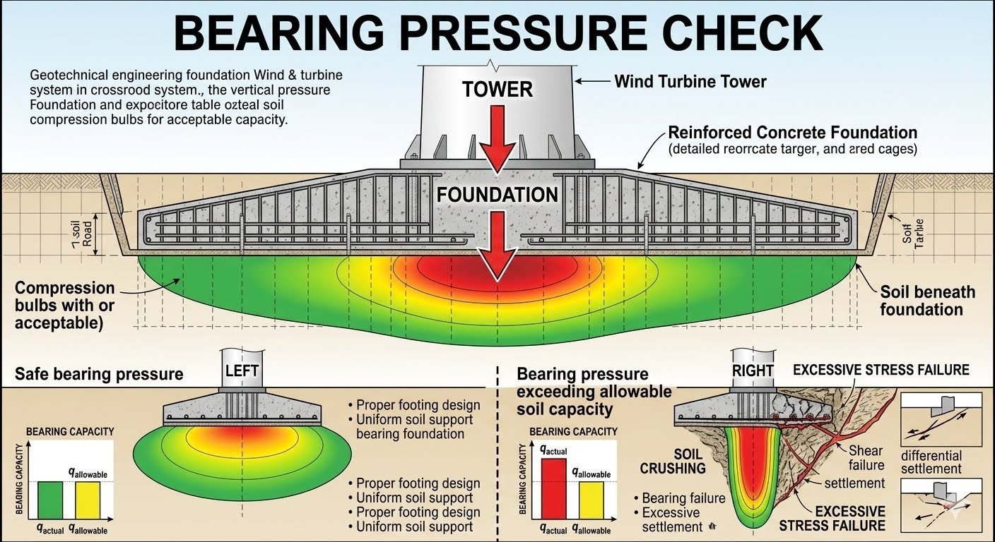
In my two decades of industrial structural and piping engineering practice, I have observed that wind turbine structural integrity relies heavily on subgrade mechanics. A comprehensive bearing pressure check evaluates how the wind turbine tower’s colossal overturning moments and dead loads transfer through the reinforced concrete foundation into the supporting soil. When designing these massive gravity-base or piled systems, structural engineers must visualize the compression bulbs spreading downward and outward from the footing interface.
Under safe bearing pressure conditions, proper footing geometry, uniform subgrade support, and adequate sizing ensure the actual pressure q_actual stays below the allowable bearing capacity q_allowable. Conversely, inadequate sizing or erratic soil support triggers severe geotechnical failures such as soil crushing, deep-seated shear failure, and differential settlement.
Key Engineering Takeaways
- Accurate calculation of eccentric load distributions under extreme wind gusts.
- Strict adherence to ASCE 7 wind loading parameters for overturning moments.
- Verification of both drained and undrained soil shear strength parameters.
- Prevention of edge-pressure overstressing through optimized octagonal or circular footing design.
Geotechnical Bearing Pressure Analysis for Wind Turbines
Executing a rigorous bearing pressure check requires dissecting complex load combinations transferred from the wind turbine tower flange to the top of the reinforced concrete pad. Wind turbines generate extreme overturning moments combined with relatively modest vertical dead loads compared to traditional buildings. This loading profile creates a high eccentricity ratio (e = M / P), where M is the overturning moment and P is the total vertical load. Consequently, the contact pressure beneath the circular or octagonal mudmat is non-uniform, shifting from a maximum compressive stress at the toe to a minimum stress—or potential uplift—at the heel.
To evaluate this stress distribution, engineers apply classical Meyerhof and Hansen bearing capacity formulations modified for large-diameter circular or annular foundations. The general bearing capacity equation incorporates shape, depth, and inclination factors:
Where c represents soil cohesion, q is the effective overburden pressure at the foundation base level, γ is the effective unit weight of the soil, B is the effective foundation width, and N_c, N_q, N_gamma are dimensionless bearing capacity factors dependent on the internal friction angle (φ).
Eccentric Loading and Effective Area Method
When wind turbine foundations experience combined vertical loads and multi-directional bending moments, the resulting pressure distribution is triangular or trapezoidal. If the eccentricity exceeds the kern limit (L/6 for rectangular sections), a portion of the foundation experiences zero contact pressure, indicating partial separation from the subgrade. In my site designs, I strictly limit the uplift zone to comply with ASCE standards, ensuring that at least 80% of the base remains in compression under 50-year extreme wind events.
The effective area method reduces the actual foundation dimensions (B’ and L’) to account for load eccentricities in both principal axes:
The maximum actual bearing pressure q_max is then evaluated across this reduced effective footprint using the eccentric foundation formula:
Critical Geotechnical Warning
Failure to account for cyclic fatigue degradation in saturated cohesive soils can lead to progressive bearing capacity reduction. Wind turbine dynamic braking and turbulent wind buffeting induce millions of load cycles, which can liquefy loose sands or soften overconsolidated clays if adequate factors of safety are not applied.
Settlement Criteria and Deformation Limits
While checking ultimate bearing capacity prevents catastrophic geotechnical shear failure, serviceability limit states often govern wind turbine foundation design. Excessive differential settlement tilts the tower shaft, inducing severe secondary bending moments in the tubular steel segments and mechanical misalignments in the nacelle drivetrain. Geotechnical engineers must calculate immediate elastic settlement, primary consolidation settlement for fine-grained soils, and secondary creep deformation.
Elastic settlement s_e is estimated using elastic continuum theory:
Where nu represents Poisson’s ratio of the soil, E_s is the soil’s Young’s modulus, I_s is the shape and rigidity factor, and q is the applied contact pressure. Differential settlement across a 20-meter diameter gravity base must be constrained to strict angular distortions, typically less than 1:500, to protect tower alignment.
Advantages
- Prevents catastrophic bearing capacity and subgrade shear failures under extreme typhoon or hurricane wind loadings.
- Minimizes differential settlement, protecting sensitive internal turbine machinery and tower shell verticality.
- Optimizes concrete and reinforcement quantities by accurately mapping eccentric pressure distributions instead of assuming uniform loading.
- Ensures compliance with international structural codes such as ISO 19901-4 and ASCE guidelines.
- Enhances long-term fatigue life of anchor cages and post-tensioned tendon assemblies.
Disadvantages
- Requires extensive, high-cost geotechnical site investigations, including cross-hole seismic testing and cyclic triaxial laboratory soil sampling.
- Complex finite element modeling is required to accurately capture soil-structure interaction and non-linear subgrade response.
- Overly conservative bearing pressure limits can lead to excessively large foundation footprints, driving up civil construction costs.
- Accounting for cyclic degradation demands specialized software packages not standard in basic structural analysis suites.
- Delays design sign-off if subsurface soil variability requires iterative foundation geometry resizing.
Onshore Mega-Wind Farms on Soft Alluvial Clays
In regions characterized by thick layers of compressible clay, standard gravity-base foundations induce excessive primary consolidation settlement. Engineers deploy deep soil mixing or rammed aggregate piers to artificially increase the composite subgrade bearing capacity, ensuring actual bearing pressures remain within safe operational limits.
Offshore Gravity-Based Foundations in Shallow Waters
Offshore gravity-base structures experience immense wave slamming forces coupled with wind turbine thrust. Bearing pressure checks must evaluate sliding stability and skirt penetration resistance in marine sand and clay deposits, preventing scouring-induced bearing capacity loss.
Complex Mountainous Ridge Wind Installations
Ridge-top wind turbine sites often feature sloping bedrock overlaid with shallow, erratic colluvium soils. Structural engineers must perform localized sliding and bearing pressure checks on stepped rock benches to prevent downhill toe breakout during extreme wind squalls.
Repowering Older Wind Turbine Sites
When upgrading legacy 1.5MW wind turbines to modern 5MW machines on existing foundation locations, bearing pressure checks verify whether the historic concrete pad can withstand doubled overturning moments and heavier nacelle dead loads without subgrade overstressing.
Wind Turbine Foundation Bearing Pressure Parameters
Evaluating geotechnical stability requires a rigorous analysis of structural loads acting against underlying soil mechanics. The engineering data table below details the essential design parameters, code limits, and typical site values utilized during a comprehensive bearing pressure check for utility-scale wind turbine gravity foundations. Every parameter directly influences the geometry and reinforcement distribution required to prevent catastrophic shear or consolidation failure.
When sizing octagonal or circular reinforced concrete mudmats, geotechnical engineers must account for extreme dynamic overturning moments transmitted from the tower tubular shell. These moments shift the resultant footing reaction force toward the leeward edge, dramatically amplifying localized edge stresses. The following matrix correlates standard design variables with established geotechnical criteria found in ASCE guidelines and shallow foundation design specifications.
| Design Parameter | Symbol & Units | Typical Range / Value | Governing Code / Standard |
|---|---|---|---|
| Actual Contact Pressure | q_actual (kPa or psf) | 150 – 350 kPa (service loads) | ASCE 7-22 Chapter 2 |
| Allowable Bearing Capacity | q_allowable (kPa or psf) | 200 – 600 kPa (soil dependent) | ASTM D6035 Standard |
| Geotechnical Safety Factor | FS (dimensionless) | 3.0 (static) / 2.0 (extreme wind) | ASCE/SEI 48 & OSHA |
| Eccentricity Ratio Limit | e / B (dimensionless) | ≤ 1/6 (kern limit for no uplift) | ACI 318-19 Building Code |
| Undrained Shear Strength | c_u (kPa) | 50 – 150 kPa (cohesive soils) | ASTM D2166 Vane Shear |
| Subgrade Modulus | k_s (kN/m^3) | 15,000 – 50,000 kN/m^3 | Winkler Foundation Model |
Note: Values shown reflect typical onshore utility installations. Actual geotechnical report parameters override generalized ranges based on site-specific core borings and pressuremeter testing.
Technical Mapping & Specifications Matrix
Modern structural engineering workflows rely on precise entity mapping to correlate physical soil properties with finite element analysis boundary conditions. The matrix below translates core geotechnical terms, structural acronyms, and standard testing methodologies into actionable design inputs. Proper integration of these parameters prevents underestimation of settlement vectors during extreme meteorological events.
By standardizing nomenclature across structural and geotechnical disciplines, engineering teams eliminate ambiguity when reviewing turbine manufacturer dynamic load sets. Every entity listed below is governed by recognized international standards, ensuring seamless compliance across global wind farm developments.
| Entity / Acronym | Full Technical Term | Engineering Definition & Application | Governing Reference |
|---|---|---|---|
| BDS | Bearing Design Stress | The localized compressive stress transferred from the pedestal ring to the top mat concrete. | ACI 318-19 Section 22.8 |
| RQD | Rock Quality Designation | Percentage of intact core pieces longer than 100mm recovered from boreholes. | ASTM D6032 Standard |
| SPT-N | Standard Penetration Test Value | Blow count required for 300mm penetration of split-barrel sampler in granular soils. | ASTM D1586 Method |
| GWT | Groundwater Table Depth | Subsurface water level location; dictates buoyant unit weight corrections for bearing capacity. | Terzaghi Bearing Theory |
| FEA | Finite Element Analysis | Numerical modeling method used to simulate non-linear soil-structure interaction bulbs. | ISO 19901-4 Offshore/Onshore |
Entity mapping ensures full traceability from raw geotechnical laboratory logs to final structural foundation reinforcement schedules.
Site Verification Checklist for Foundation Bearing
Ensuring that actual field conditions match geotechnical design assumptions requires rigorous, step-by-step verification before concrete placement. Field engineers must systematically inspect excavation subgrades, verify reinforcing steel placement, and confirm compaction density. Skipping any verification step can lead to localized soft spots, uneven settlement bulbs, and premature tower tilting.
The following checklist outlines mandatory inspection milestones required by ASCE standards and wind turbine original equipment manufacturer (OEM) specifications. Each checkpoint must be signed off by a qualified geotechnical engineer before blinding concrete is poured.
Pre-Pour & Geotechnical Verification Protocol
- Subgrade Inspection: Verify that the bottom of the excavation matches the geotechnical report elevation and exposes competent bearing stratum free of organic matter, debris, or weathered pockets.
- Dynamic Cone Penetrometer (DCP) Testing: Conduct in-situ DCP or hand penetrometer tests across the excavation footprint to confirm uniform soil stiffness matches design assumptions.
- Groundwater Control: Confirm dewatering systems are actively maintaining water levels at least 500mm below the subgrade elevation to prevent piping and softening.
- Blinding Concrete Layer: Place a minimum 75mm thick lean concrete mudmat immediately following subgrade approval to protect soil from moisture degradation and provide a clean working platform.
- Reinforcement & Anchor Cage Alignment: Inspect bottom mat rebar spacing, cover blocks, and anchor chair positioning against structural drawing tolerances before concrete batching begins.
Completion of this checklist forms a permanent quality assurance record. Any deviation in soil bearing capacity observed during excavation must be reported immediately to the geotechnical engineer of record for re-evaluation.
Field Case Study: Real-World Application
Real-world engineering challenges frequently expose the limitations of idealized geotechnical models. The following case study examines a 3.4 MW wind turbine installation on a complex coastal site where inadequate initial bearing pressure evaluations led to severe differential settlement, requiring complex remediation under operational deadlines.
Field Problem: Unanticipated Clay Lens and Edge Overstress
During commissioning of a 3.4 MW wind turbine on a coastal wind farm, routine geodetic monitoring revealed an abnormal tilt exceeding 4.5 millimeters across the tower flange. Initial design reviews assumed a homogenous dense sand stratum across the entire octagonal foundation footprint. However, post-construction forensic investigations uncovered a localized, compressible organic clay lens spanning beneath one quadrant of the footing. Under sustained operational thrust and extreme wind gusts, the actual contact pressure on the softer clay pocket significantly exceeded the allowable soil bearing capacity, triggering progressive foundation tilting.
- Inadequate exploratory borehole spacing failing to detect the buried compressible clay lens.
- Actual edge bearing pressure (q_actual) surging past the allowable limit (q_allowable) by 38% during high-wind events.
- Absence of continuous subgrade stiffness verification during the initial excavation phase.
- Accelerated differential settlement causing internal tower operational alarm triggers.
Field Outcome: Successful Micropile Underpinning & Stabilization
To arrest the ongoing differential settlement and restore structural integrity without dismantling the turbine, the engineering team executed a comprehensive emergency stabilization program. Four high-capacity steel-cased micropiles were drilled through pre-cored sleeves in the existing concrete mat down to competent bedrock. The load was successfully transferred from the overstressed soil stratum into the deep rock anchors via post-installed hydraulic load-transfer brackets. Subsequent geodetic monitoring confirmed complete stabilization, bringing the turbine back to operational status within strict OEM tilt tolerances.
- Successful load transfer reducing maximum soil bearing pressure by 52% across the affected quadrant.
- Complete cessation of differential settlement verified over a 12-month post-repair monitoring period.
- Adoption of revised geotechnical testing protocols requiring continuous cross-hole sonic logging for future phases.
- Avoidance of catastrophic tower collapse and multi-million dollar turbine replacement costs.
Recommendation: Always enforce a minimum exploratory boring density of one borehole per turbine location, supplemented by continuous geophysical refraction profiling in complex coastal or alluvial terrains.
Frequently Asked Engineering Questions
What is the primary objective of a wind turbine foundation bearing pressure check?
- Prevents localized soil crushing and shear failure beneath the mudmat.
- Limits long-term differential settlement to protect sensitive turbine internals.
- Guarantees a reliable factor of safety against overturning under extreme wind loads.
How do extreme overturning moments affect maximum soil bearing pressure?
What distinguishes allowable bearing capacity from ultimate bearing capacity?
- Ultimate capacity is derived using Terzaghi or Meyerhof bearing capacity equations.
- Allowable capacity typically incorporates a safety factor ranging from 2.5 to 3.0.
- Serviceability limits often govern allowable capacity long before ultimate shear failure occurs.
How does soil stiffness variation cause differential settlement in gravity bases?
- Induces secondary bending moments and torsional stresses in the tower anchor cage.
- Can tilt the wind turbine out of vertical alignment, accelerating gearbox fatigue.
- Requires comprehensive subsurface geotechnical investigations prior to final foundation sizing.
What mitigation steps are taken when bearing pressure exceeds soil capacity?
- Enlarge the footing diameter or pad width to distribute loads over a larger surface area.
- Install rammed aggregate piers, vibro-replacement stone columns, or driven steel piles.
- Excavate poor subgrade soils and replace them with engineered, compacted structural fill.
Field Recommendation
As a piping and structural engineering specialist reviewing heavy foundation designs, I advise prioritizing strict adherence to geotechnical subgrade limits during the initial planning phase rather than relying on costly retrofits later.
- If soil borings reveal erratic compressible layers within two footing widths beneath the subgrade, choose deep pile support or stone columns immediately rather than expanding a shallow gravity base, because cyclic wind overturning moments will inevitably trigger differential settlement.
- If actual bearing pressure calculations approach 90 percent of the allowable geotechnical limit under extreme operational wind gusts, reject the baseline pad geometry and increase the footing diameter by at least 15 percent to establish a safe engineering margin.
- If construction takes place in freeze-thaw sensitive soils, specify a granular leveling mudmat and frost-protected perimeter insulation to prevent seasonal heave from disrupting the uniform soil-structure contact interface.
- If dynamic soil-structure interaction reports indicate potential resonance during extreme turbine braking events, require full-scale plate load testing on site to verify the actual subgrade modulus before pouring high-strength structural concrete.
Complete Course on
Piping Engineering
Check Now
Key Features
- 125+ Hours Content
- 500+ Recorded Lectures
- 20+ Years Exp.
- Lifetime Access
Coverage
- Codes & Standards
- Layouts & Design
- Material Eng.
- Stress Analysis
