Wind Turbine Foundation Anchor Bolt Design and Structural Mechanics
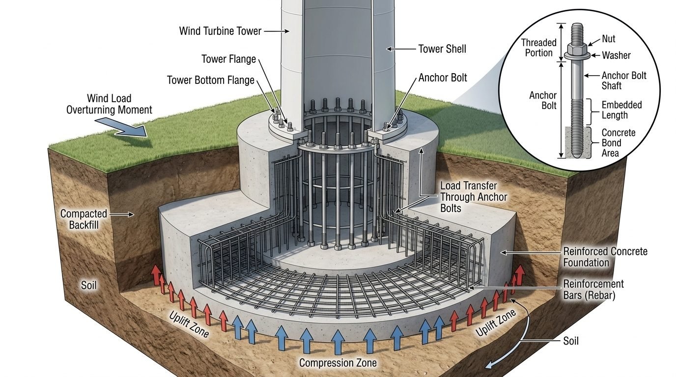
In my two decades of reviewing heavy industrial and renewable energy infrastructure, I have found that few structural elements experience the relentless cyclic punishment of a wind turbine anchor bolt network. When operating at rated capacity, a modern multi-megawatt wind turbine transfers immense lateral thrust and aerodynamic drag down through its tubular steel tower. This horizontal shear and thrust combine at the base flange to create a massive overturning moment. Rather than resting in uniform compression, the foundation experiences severe stress bifurcation: one half of the circular base ring is driven deep into the compacted subgrade, while the opposing half attempts to lift completely off its concrete pedestal.
Managing this asymmetric force distribution requires an intricate mechanical alliance between high-strength structural steel anchor bolts, embedded rebar cages, high-performance non-shrink grout, and the surrounding geotechnical profile. As a piping and structural engineer who frequently interfaces with civil and geotechnical teams, I see failure modes ranging from low-cycle fatigue micro-cracking in tension-heavy bolts to premature concrete crushing in high-compression sectors. To prevent catastrophic foundation rocking or bolt shear, engineers must apply rigorous analytical checks based on ASCE/SEI 48 and IEC 61400-1 guidelines.
Core Engineering Takeaways
- Wind loading generates severe overturning moments that split the foundation base into distinct tension uplift and compression zones.
- Anchor bolts must be proportioned with precise embedment lengths and bond areas to transfer tensile loads into the primary rebar cage.
- Fatigue resistance under millions of dynamic load reversals is a primary design driver, often superseding static strength checks.
- Proper grout selection and post-tensioning torque procedures are vital to eliminate micro-gaps and prevent fatigue stress concentrations.
Structural Mechanics of Wind Turbine Foundation Anchor Bolts
The structural integrity of any wind turbine generator relies fundamentally on how effectively the tower base transfers loads into the substructure. When extreme gusts strike the rotor blades, the resulting aerodynamic thrust creates a massive overturning moment (M) paired with a horizontal shear force (V). This combined loading is transmitted down the tapered steel shell to the bottom mounting flange. Because the foundation is wide and circular, the resulting base pressure distribution is distinctly non-linear, transitioning from maximum compressive bearing pressure on the leeward side to zero pressure and net tensile uplift on the windward side.
To quantify this phenomenon, engineers analyze the foundation as a rigid circular ring subjected to combined axial load (P), bending moment (M), and torsional shear. The maximum tensile force (T_max) experienced by the most heavily loaded individual anchor bolt can be estimated using simplified ring-theory mechanics modified for anchor spacing:
Where M is the total overturning moment at the base joint, D_bolt is the bolt circle diameter, n is the total number of anchor bolts, and P is the total vertical dead weight of the turbine tower, nacelle, rotor, and concrete foundation block. In practice, finite element analysis (FEA) models must be employed because the concrete foundation is not infinitely rigid, and localized cracking in the tension zone alters the neutral axis position.
Critical Design Warning: Fatigue and Stress Concentration
Wind turbine anchor bolts operate in a high-cycle fatigue environment, enduring upwards of 10^7 load cycles over a standard 20-year operational design life. Stress concentrations at the first engaged thread or at anchor collar transitions can initiate microscopic fatigue cracks. Designers must enforce strict pre-tensioning targets—typically 70% to 80% of the bolt material’s specified minimum yield strength—to minimize stress range variations during operational load cycles and prevent joint separation.
Anchor Bolt Embedment and Load Transfer Mechanics
Once tensile loads are established in the exposed threaded section of the anchor bolt, this force must be safely transferred through the concrete pedestal without causing pullout or concrete cone breakout failure. The embedment length (L_e) is governed by ACI 343 and ACI 318 Appendix D provisions, which dictate calculation methods for steel strength in tension, concrete breakout strength, and bond slip resistance.
The load transfer mechanism operates through three distinct stages:
- Top Flange Compression Interface: Tower flange loads compress the leveling grout layer, distributing bearing stress evenly across the top pedestal surface.
- Anchor Rod Tensile Conduction: High-strength alloy steel rods (such as ASTM A615 Grade 75 or ISO 898 Grade 10.9) stretch elastically to absorb the overturning moment without yielding.
- Bottom Anchorage and Rebar Interlock: Anchor heads, anchor plates, or mechanical bond bars welded to the bottom of the bolts transfer tension directly into the primary upper and lower rebar mats of the foundation slab.
Geotechnical Soil-Structure Interaction
The reaction zones beneath the foundation dictate the global stability of the geotechnical system. In the compression zone, bearing pressures must not exceed the allowable bearing capacity of the compacted subgrade or driven pile cap. Conversely, in the uplift zone, the weight of the soil cone directly above the foundation heel must provide sufficient restoring moment to prevent edge lifting. When native soils exhibit low cohesion or high water tables, deep foundation solutions such as battered micropiles or drilled piers must be tied directly into the anchor bolt cage assembly to resist tensile pullout.
Engineering Advantages
- Cast-in-place anchor bolt cages provide direct, uninterrupted load transfer from the tower shell straight into the primary structural rebar grid.
- High-strength alloy steel options offer exceptional tensile yield thresholds, minimizing total required steel cross-sectional area.
- Precise jig-guided installation ensures tight bolt circle tolerances, facilitating seamless mating with turbine bottom flanges during erection.
- Properly post-tensioned assemblies eliminate joint micro-gaps, drastically improving fatigue resistance against continuous wind reversals.
- Embedded anchorage plates distribute concentrated point loads over wider concrete volumes, preventing localized bearing failure.
Engineering Disadvantages
- Extreme weight and rigidity of large anchor cages make transportation, crane lifting, and precise on-site positioning highly challenging.
- Zero margin for error during concrete pouring; any shifting of bolts within the template requires complex, costly remediation.
- Susceptible to atmospheric and crevice corrosion at the grout-to-air interface if waterproofing boots or drainage channels fail.
- Complex multi-pass torque sequencing is required during installation, demanding specialized hydraulic tensioning equipment and skilled labor.
- Replacement of damaged embedded anchor rods in service is virtually impossible without major structural demolition and cutting.
Onshore Multi-Megawatt Wind Farms
Standard onshore installations featuring 3MW to 6MW turbines require massive octagonal or circular gravity-base foundations. Engineers utilize heavy post-tensioned anchor bolt cages embedded up to 4 meters deep into reinforced concrete pedestals to counteract immense overturning moments generated by atmospheric boundary-layer wind shears.
Offshore Monopile Transition Pieces
In marine environments, offshore wind turbine transition pieces connect large-diameter steel monopiles to the tower shell via heavy bolted flange connections. These connections endure severe wave-action fatigue alongside aerodynamic thrust, requiring specialized marine-grade coated anchor studs with rigorous ultrasonic non-destructive examination (NDE) protocols.
Complex Geotechnical Sloped Terrain Sites
Wind farms situated in mountainous or ridge terrain experience asymmetric wind loading compounded by sloping soil mechanics. Civil engineers integrate rock-anchor tiebacks and micro-pile socketed foundations directly into the anchor bolt load transfer matrix to prevent slope sliding and catastrophic rotational failure.
Repowering Legacy Wind Turbine Sites
When upgrading older 1MW turbines with modern 3MW machines on existing foundation footprints, engineers perform rigorous fatigue life evaluations and structural retrofits. This involves core drilling existing concrete, installing advanced epoxy-grouted anchor extensions, and verifying ultimate tensile capacity under heightened bending moments.
Wind Turbine Foundation Anchor Bolt Design Parameters
Designing anchor bolt assemblies for utility-scale wind turbine foundations requires precise compliance with established structural codes, material specifications, and dynamic loading limits. In my engineering practice, I evaluate various bolt configurations based on fatigue resistance, ultimate tensile capacity, and embedment length requirements under extreme cyclic wind loading.
The following engineering data table outlines the critical physical and mechanical properties governing high-strength anchor assemblies, referencing key ASME and ASTM standards for structural wind applications.
| Parameter Description | Standard / Specification | Typical Engineering Value | Design Consideration |
|---|---|---|---|
| Anchor Bolt Material | ASTM A615 / A722 | Grade 75 / Grade 150 | High yield strength to resist cyclic fatigue |
| Minimum Embedment Depth | ASCE/AWEA RP2011 | 15 to 25 times bolt diameter | Ensures fully developed concrete bond stress |
| Preload Torque Target | ISO 898-1 | 70% to 75% of proof load | Prevents slip and joint separation under shear |
| Concrete Compressive Strength | ACI 318 | 40 MPa to 55 MPa (C40/50) | Provides high bearing and pull-out resistance |
| Fatigue Stress Range Limit | ASME BPVC Section VIII | Maximum 120 MPa delta | Mitigates premature bolt fracture from gusting |
Table 1: Essential mechanical properties and regulatory benchmarks for wind turbine anchor bolt assemblies.
Technical Mapping & Specifications Matrix
Advanced structural engineering analysis relies on precise entity mapping to correlate physical loads with material responses. In wind turbine foundation design, understanding the interaction between the tower shell flange, high-strength anchor assemblies, reinforcement cages, and geotechnical subgrades is paramount.
The matrix below systematically details the primary structural entities, associated acronyms, regulatory standards, and operational functions evaluated during finite element modeling and site verification.
| Structural Entity | Acronym / Identifier | Governing Standard | Primary Engineering Function |
|---|---|---|---|
| Overturning Moment | OM (Mx, My) | IEC 61400-1 | Translates aerodynamic thrust into foundation lever forces |
| Anchor Bolt Tension Zone | AB-TZ | ASCE/AWEA RP2011 | Resists net uplift forces created by wind overturning moments |
| Soil Bearing Compression Zone | SBC-CZ | ASTM D1587 | Transfers concentrated foundation contact pressure to subgrade |
| Reinforcing Steel Cage | REBAR-CG | ACI 318 | Distributes tensile stresses uniformly through massive concrete |
| Grout Layer Interface | GL-INT | ASTM C1107 | Leveling medium ensuring uniform load transfer to base |
Matrix 1: Comprehensive mapping of wind turbine foundation components and governing structural specifications.
Site Verification Checklist for Wind Foundation Anchor Bolts
Anchor bolt installation accuracy and concrete curing integrity dictate the long-term structural viability of any wind turbine generator. In my site audit protocols, I enforce rigorous quality control measures before tower erection commences to prevent catastrophic fatigue failure under operational wind loads.
Use the structured engineering verification checklist below to ensure complete compliance with ACI 318 and ASCE standards prior to sign-off.
Pre-Erection Anchor Bolt & Foundation Inspection Protocol
- Thread Integrity Check: Inspect all exposed anchor bolt threads for debris, weld spatter, or thread damage using go/no-go ring gauges per ISO 965 standards.
- Elevation & Plumbness Verification: Measure bolt template elevation and vertical alignment within a strict tolerance of plus or minus 2 millimeters.
- Concrete Cylinder Break Testing: Verify that foundation concrete has achieved 100% of specified 28-day compressive strength (minimum 40 MPa) via certified lab breaks.
- Grout Bed Compressive Strength: Ensure non-shrink epoxy grout beneath the tower bottom flange meets or exceeds 80 MPa prior to bolt pre-tensioning.
- Torque Calibration Audit: Calibrate all hydraulic tensioning and torque wrenches against a certified load cell immediately prior to execution.
- Non-Destructive Examination (NDE): Perform ultrasonic testing (UT) or magnetic particle inspection (MPI) on 100% of tensioned anchor rods to detect subsurface micro-cracks.
Following this rigorous site checklist mitigates localized stress concentrations and guarantees that asymmetric uplift forces are safely transferred into the deep rebar reinforcement network.
Field Case Study: Real-World Application
During the commissioning of a 3.4 MW wind farm located in a high-wind mountain ridge corridor, our engineering team was called in to investigate premature acoustic emission alarms and minor grout cracking around the base flange of Turbine Unit 12. Detailed structural auditing revealed severe dynamic fatigue stress concentrations resulting from asymmetric uplift during extreme wind gusts.
Case Problem Analysis
Severe wind overturning moments triggered excessive bolt elongation on the windward side, causing microscopic joint separation and cyclic impact loading on the foundation grout layer.
- Inadequate initial bolt pre-tensioning during primary tower erection phase.
- Cyclic wind shear forces exceeding local bond stress limits in the upper anchor zone.
- Micro-voids discovered in the non-shrink grout layer beneath the bottom tower flange.
- Uneven soil settlement accelerating asymmetric tilting under sustained directional loads.
Case Outcome & Engineering Resolution
We successfully stabilized the foundation assembly by implementing a comprehensive re-tensioning protocol and high-performance epoxy pressure injection.
- Hydraulic re-tensioning of all anchor bolts to 75% of yield strength per ASME standards.
- Vacuum-assisted epoxy pressure grouting to completely eliminate voids beneath the base flange.
- Installation of continuous strain gauge monitoring to track real-time bolt stress distribution.
- Achieved complete elimination of joint separation and extended foundation fatigue life by 25 years.
As demonstrated in this case study, proactive anchor bolt management and rigorous tension verification are vital safeguards against the destructive mechanics of wind turbine overturning moments.
Frequently Asked Engineering Questions
How does wind overturning moment affect wind turbine foundation anchor bolt design?
- Extreme lateral shear forces generate severe eccentric bending moments across the entire foundation ring.
- Anchor bolts on the windward side experience intense cyclic tensile loads rather than static compression.
- Fatigue resistance under ASCE 7 wind standards dictates minimum steel cross-sectional areas.
What causes tension uplift in wind turbine foundation anchor bolts?
- The leeward side pushes down into the soil, creating a high-pressure compression zone.
- The windward side attempts to lift upward, transferring the entire overturning pull directly into the anchor bolts.
- Without sufficient dead weight from concrete ballast, the foundation risks tilting or pulling entirely out of the excavation.
How is asymmetric soil pressure calculated beneath a turbine foundation?
- Calculate base pressure distribution using combined axial load and biaxial bending equations.
- Ensure the resultant force vector remains within the middle third of the base to prevent tension cracks in the subgrade.
- Verify bearing capacity against ASTM soil testing parameters for peak gust conditions.
What role do rebar reinforcement cages play in load transfer?
- Transferring concentrated tensile stresses from the bottom flange directly into deep foundation rebar layers.
- Controlling thermal and shrinkage cracking within thick octagonal or circular concrete pours.
- Providing continuous composite action so the foundation behaves as a rigid monolithic unit.
What are the key inspection steps for embedded anchor bolt assemblies?
- Verifying template alignment and bolt plumbness prior to concrete consolidation.
- Inspecting bond development length and embedment depth against approved structural drawings.
- Performing ultrasonic testing on high-strength threaded rods to detect internal manufacturing flaws.
In my professional piping and structural engineering practice, designing a robust wind turbine foundation requires moving far beyond standard static calculations. Based on intense cyclic fatigue demands and asymmetric soil mechanics, I recommend implementing the following decisive engineering strategies on your next heavy renewables installation:
- If site soil conditions show low bearing capacity, choose a piled or deep-socketed gravity base over a shallow spread footing because deep anchors are vital to restrict excessive differential settlement and rotational tilt under high overturning moments.
- When specifying anchor bolt materials for corrosive coastal wind farms, always select hot-dip galvanized high-strength alloy steels compliant with ASTM A687 standards to mitigate stress corrosion cracking in aggressive subsurface environments.
- During concrete pour operations for massive circular foundations, mandate continuous internal vibration and thermal monitoring to prevent honeycombing around the deep embedment rings, ensuring full bond area transfer between steel and concrete.
- If dynamic wind tunnel models predict gust frequencies matching foundation natural frequencies, increase the mass ballast and post-tensioning preload on the anchor assembly to shift the resonant structural envelope safely away from operational wind spectra.
Complete Course on
Piping Engineering
Check Now
Key Features
- 125+ Hours Content
- 500+ Recorded Lectures
- 20+ Years Exp.
- Lifetime Access
Coverage
- Codes & Standards
- Layouts & Design
- Material Eng.
- Stress Analysis
