Engineering Wind Turbine Components From Rotor Blades to Soil Foundations
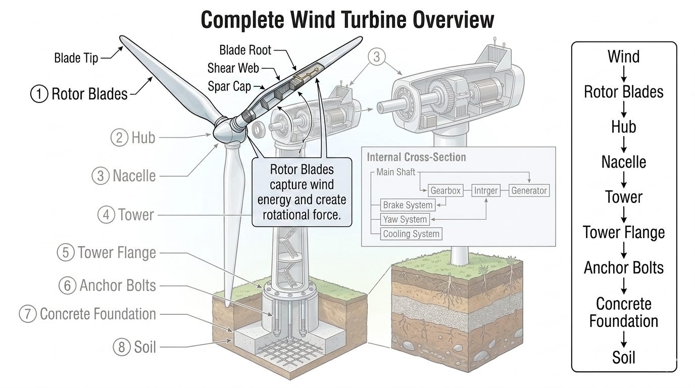
In my twenty years managing complex structural and mechanical engineering installations, few systems demand as rigorous an integrated load path as utility-scale wind turbines. When evaluating wind turbine components, engineers cannot look at mechanical assemblies in isolation from the geotechnical foundation. Every Newton of force captured at the rotor tips generates bending moments, shear forces, and dynamic fatigue cycles that must travel uninterrupted through the nacelle, tower, anchor bolts, and concrete mat before reaching the earth.
Understanding this continuous structural chain is what separates reliable renewable energy assets from premature component failures. In this guide, I break down the complete top-to-bottom hierarchy, examining the physical constraints, stress concentrations, and design standards governing each tier of modern turbine architecture.
Key Engineering Takeaways
- The complete load path requires uninterrupted transfer of aerodynamic thrust and gravitational loads across eight distinct structural tiers.
- Rotor blade design centers on composite spar caps and shear webs resisting extreme flapwise and edgewise bending moments.
- Tower flanges and high-strength anchor bolts form the critical transition zone between dynamic tubular steel structures and massive concrete foundations.
- Geotechnical soil-structure interaction ultimately dictates the allowable overturning moment and dynamic stiffness of the entire installation.
Structural Hierarchy and Load Path of Wind Turbine Components
Designing utility-scale wind generators demands an uncompromising focus on the eight-tier load path. When wind strikes the turbine, the mechanical journey begins at the aerodynamic boundary layer of the rotor blades. As an engineering manager, I always remind junior designers that each component downstream must be sized not just for nominal operating loads, but for extreme 50-year gust scenarios governed by IEC 61400-1 design requirements.
Let us examine the top four tiers of the structural hierarchy: Rotor Blades, the Hub, the Nacelle, and the Tower. Each tier introduces distinct failure modes, material selections, and vibrational characteristics that dictate overall asset reliability.
1. Aerodynamic Capture: Rotor Blades and Spar Design
The rotor blades represent the primary energy conversion interface. Composed of high-performance glass-fiber or carbon-fiber reinforced epoxy composites, modern blades feature a complex internal anatomy including the blade tip, aerodynamic root, central shear web, and load-bearing spar caps.
The spar caps act as the main structural girders, absorbing the massive flapwise bending moments induced by wind thrust. The shear webs tie the upper and lower spar caps together, preventing torsional buckling and transferring shear forces out to the blade root.
Engineering Warning: Edge-Wise and Flap-Wise Fatigue
Rotor blades experience severe cyclic fatigue driven by wind shear, tower shadow effects, and atmospheric turbulence. Failure to properly model delamination in composite spar caps under combined bending and centrifugal loading can lead to catastrophic blade shedding during high-wind shutdown events.
2. Mechanical Transmission: Hub, Main Shaft, and Nacelle Internal Assembly
The cast steel rotor hub aggregates the kinetic output of the individual blades, transferring rotational torque directly into the low-speed main shaft housed within the nacelle. The nacelle serves as the environmental enclosure and structural backbone for the internal mechanical assembly.
Inside the nacelle, the drive train typically incorporates a multi-stage planetary and helical gearbox to step up rotational velocity before it reaches the electrical generator. Furthermore, the nacelle houses the hydraulic or electromechanical yaw system, which actively rotates the entire housing to keep the rotor perpendicular to changing wind vectors.
Thermal management is equally critical within this enclosure. High-capacity cooling systems circulate glycol-water mixtures through the generator windings and gearbox oil coolers to dissipate the tremendous thermal energy generated during continuous megawatt-scale power generation.
3. Structural Support: Towers, Flanges, and Foundation Transfer
Once rotational energy is converted to electricity, the entire weight of the nacelle and rotor—often exceeding 400 metric tons on modern 5MW+ turbines—rests upon the tubular steel or hybrid concrete tower. The tower must possess immense buckling resistance while remaining flexible enough to avoid resonant frequencies matching the passing blade frequency (1P and 3P harmonics).
At the base of the tower lies the heavy structural tower flange. This precision-machined steel ring connects the tubular tower shell to the foundation anchor bolt cage using high-tensile pre-tensioned studs. These anchor bolts transfer extreme tensile overturning moments directly into the massive reinforced concrete foundation slab.
Finally, the concrete foundation distributes the concentrated structural loads across a wide footprint into the native soil. The soil’s bearing capacity and dynamic shear modulus dictate the final settlement limits and rotational stiffness of the entire renewable energy installation.
Engineering Advantages
- Modular Transportability: Segmented tower and bolted flange designs allow transport of massive structural members via standard highway logistics.
- Predictable Load Paths: Clear hierarchical load transfer from rotor blades to soil simplifies finite element modeling and compliance verification.
- Advanced Material Efficiency: High-modulus carbon-fiber spar caps maximize aerodynamic span while minimizing gravitational dead weight.
- Redundant Safety Systems: Independent aerodynamic braking and mechanical disc brakes provide failsafe rotor arrest during grid loss.
- Standardized Geotechnical Design: Well-established gravity mat and pile-cap foundation standards streamline civil engineering approvals.
Engineering Disadvantages
- Complex Fatigue Interaction: Multiaxial cyclic loading accelerates bolted flange relaxation and micro-crack propagation in welded joints.
- High Logistics Overhead: Transporting 80-meter rotor blades and heavy nacelle castings requires specialized crane spreads and road permits.
- Geotechnical Sensitivity: Soft soil profiles necessitate expensive deep-piled foundation solutions to prevent excessive tilt and settlement.
- Maintenance Access Challenges: High-altitude nacelle components demand specialized lifting gear and weather-dependent offshore or onshore interventions.
- Thermal Constraints: Enclosed nacelle environments trap heat, requiring robust active cooling systems to protect sensitive electrical drives.
Onshore Plain and Ridge Installations
Onshore wind farms constructed across high-altitude ridges utilize deep gravity concrete foundations tied directly to dense bedrock. Engineers must account for severe wind turbulence and icing conditions that increase dynamic dead loads on rotor blades and tower flanges.
Offshore Fixed-Bottom Monopile Farms
Marine environments require massive steel monopiles driven deep into seabed soil strata to replace traditional onshore concrete mats. The transition piece and bolted flange must endure aggressive wave slamming and corrosive saltwater exposure while supporting towering multi-megawatt nacelles.
Floating Offshore Deepwater Platforms
For deepwater deployment where fixed foundations are economically unviable, semi-submersible or tension-leg platforms replace traditional soil interfaces. Mooring lines and dynamic ballasting systems maintain structural stability under combined wave and wind bending moments.
Complex Terrain and Forested Sites
Forested and complex mountainous terrain introduces extreme wind shear profiles and restricted transport logistics. Engineers utilize sectional hybrid steel-concrete towers and specialized modular rotor blade assembly techniques to overcome site access constraints.
Wind Turbine Component Specifications and Standards
Engineering evaluation of utility-scale wind turbine structures requires strict adherence to international design codes. The structural integrity of each tier in the eight-tier assembly depends on rigorous material selection, fatigue analysis, and load-path verification under extreme environmental conditions. When examining wind turbine components, engineers must cross-reference multiple governing standards including IEC 61400, ASCE 7, and DNVGL-ST-0126 to ensure long-term operational safety.
The data matrix below outlines the primary structural tiers, their principal materials of construction, dominant failure modes, and the governing international standards required for comprehensive turbine structural design. Reviewing these parameters allows structural engineers to mitigate fatigue risks and optimize load transfer from the rotor blades down to the supporting soil profile.
| Component Tier | Primary Material | Dominant Failure Mode | Governing Standard |
|---|---|---|---|
| Rotor Blades | Epoxy-Glass/Carbon Fiber Composite | Delamination, Edge-wise Fatigue, Lightning Strike | IEC 61400-5 |
| Hub & Nacelle | Ductile Cast Iron (EN-GJS-400-18U) | Micro-cracking, Bearing Seizure, Gearbox Wear | IEC 61400-4 |
| Tower Shell | Structural Steel (S355NL / ASTM A572) | Global Buckling, Vortex-Induced Vibration | DNVGL-ST-0126 |
| Tower Flange & Bolts | High-Strength Alloy Steel (Grade 10.9) | Bolt Relaxation, Fatigue Yielding, Thread Galling | VDI 2230 |
| Foundation & Soil | Reinforced Concrete & Geo-stratum | Overturning, Sliding, Soil Bearing Failure | ACI 318 / ASCE 7 |
Table 1: Comprehensive summary of mechanical and civil parameters across the eight-tier wind turbine load path hierarchy.
Technical Mapping & Specifications Matrix
System integration within modern wind energy installations demands precise entity mapping to correlate physical hardware with analytical modeling parameters. In my professional practice, I rely on standardized metadata matrices to track structural interfaces, load transfer coefficients, and regulatory compliance milestones. This structured approach prevents interface mismatches between mechanical assemblies provided by turbine original equipment manufacturers and civil works designed by local engineering consultants.
The entity mapping matrix below establishes the direct relationships between physical structural elements, their primary engineering functions, and associated design standards. Utilizing this matrix ensures that every element in the load path from aerodynamic capture to geotechnical resistance is accounted for during the front-end engineering design phase.
| Structural Entity | Primary Engineering Function | Design Parameter | Compliance Reference |
|---|---|---|---|
| Aerodynamic Rotor | Kinetic energy extraction into torque | Tip Speed Ratio (Lambda) > 8.0 | IEC 61400-1 |
| Drivetrain Assembly | Mechanical torque amplification and generation | Gear Ratio & Thermal Dissipation | AGMA 6006 |
| Tubular Tower | Elevation of nacelle and moment resistance | Natural Frequency > 1P/3P Band | GL-IV-1 |
| Anchor Bolt Cage | Tensile force transmission to foundation | Preload Torque > 70% Yield | AISC 360 |
| Geotechnical Interface | Ultimate load absorption and settlement control | Bearing Capacity Factor > 3.0 | ASTM D1587 |
Table 2: Entity mapping specification outlining critical design parameters and international standard compliance.
Site Verification Checklist
Site verification and quality control during wind turbine installation require meticulous adherence to engineering specifications. Before any structural tier is signed off, construction teams must validate torque values, alignment tolerances, and material certifications. Neglecting any single checkpoint in the installation sequence can lead to catastrophic fatigue failures during operational service.
The following verification checklist outlines the essential field inspections required for validating the structural hierarchy of a utility-scale wind turbine installation, ensuring full compliance with renewable energy engineering best practices.
Wind Turbine Installation & Verification Protocol
-
Rotor Blade Pre-Assembly Inspection: Inspect blade root inserts, shear web bonds, and lightning protection continuity per IEC 61400-5 guidelines.
-
Nacelle Internal Alignment: Verify main shaft bearing clearance, gearbox torque arm mounting, and yaw gear backlash measurements.
-
Tower Section Plumbness & Leveling: Measure flange perpendicularity using laser interferometry to ensure deviation remains below 1 mm per meter of height.
-
Tower Flange Bolt Tensioning: Execute multi-pass hydraulic tensioning on anchor bolts and ring flanges following VDI 2230 torque calibration standards.
-
Foundation Concrete Curing Verification: Review compressive strength core test results and verify grout pad integrity under the base ring per ACI 318.
-
Geotechnical Soil Compaction Audit: Confirm backfill density and shear strength parameters against original geotechnical boring logs.
Field Case Study: Real-World Application
During the construction phase of a 50-turbine wind farm located in a high-wind mountain pass, our engineering team encountered a critical structural discrepancy at the tower flange and anchor bolt interface during final commissioning. Proper load transfer from the upper mechanical tiers down to the concrete foundation was severely compromised by installation deviations.
Field Case Problem: Anchor Bolt Preload Relaxation and Grout Voiding
Preload loss across the base ring anchor bolts was detected during dynamic load testing, accompanied by localized micro-cracking in the underlying structural grout layer.
- • Inadequate initial torque calibration during multi-pass hydraulic tensioning operations.
- • Temperature fluctuations causing differential thermal expansion between the steel tower flange and concrete foundation.
- • Sub-standard non-shrink grout mixing water ratios resulting in bleeding and honeycombing beneath the base ring.
- • Severe cyclic bending moments from extreme wind gusts accelerating bolt fatigue wear.
Field Case Outcome: Comprehensive Remediation and Load Path Restoration
Implementing a rigorous engineering remediation protocol successfully restored the structural load path and ensured long-term operational stability.
- • Re-tensioned all anchor bolts to 80 percent of yield strength utilizing ultrasonic elongation measurement per VDI 2230.
- • Executed high-pressure epoxy pressure grouting to completely eliminate voids beneath the annular base ring.
- • Installed continuous acoustic emission sensors for real-time monitoring of bolt tension and structural vibration.
- • Established a mandatory quarterly torque-audit schedule for the first two years of commercial operation.
Expert Recommendation: For complex wind turbine installations, always mandate third-party independent verification of foundation grouting and bolt tensioning. Integrating continuous health monitoring systems at the tower-to-foundation interface prevents premature structural degradation and ensures compliance with IEC 61400 reliability standards.
Frequently Asked Engineering Questions
How do shear webs and spar caps function within rotor blades?
- Spar caps run longitudinally along the inner surface of the upper and lower shell to carry primary bending moments induced by aerodynamic thrust.
- Shear webs act as vertical shear-transfer elements connecting the top and bottom spar caps, preventing cross-sectional buckling.
- Engineers design these composite structures to comply with IEC 61400-1 standards for fatigue and extreme gust loading.
What specific roles do the nacelle and gearbox play in the drive train?
- The low-speed main shaft transfers immense rotational torque from the rotor hub into the multi-stage gearbox.
- The gearbox steps up rotational velocity from roughly 10-20 RPM to 1,500-1,800 RPM required by standard high-speed generators.
- Maintenance engineers must account for thermal management inside the nacelle housing, typically utilizing forced-air cooling systems per ISO 8528 specifications.
How are tower flanges and anchor bolts engineered to resist fatigue?
- Tower flanges feature thick forged steel rings drilled precisely to accept high-strength pre-tensioned anchor bolts.
- Anchor bolts must be tensioned to exact elongation thresholds to prevent joint separation and bolt fatigue failure under reversing wind shear.
- Non-shrink structural grouting is placed beneath the base flange to ensure uniform load transfer into the concrete foundation per ASCE 7 design guidelines.
What factors govern concrete foundation design for modern turbines?
- Geotechnical investigations dictate footing dimensions to ensure bearing pressure limits on supporting soil layers are never exceeded.
- Reinforcing steel cages must resist high shear and moment stresses across multi-decade operational lifecycles.
- Waterproofing and corrosion inhibitors are routinely specified to protect embedded steel components from aggressive subsurface moisture.
How does the soil bearing interface complete the structural load path?
- Soil settlement must be strictly monitored during construction to prevent differential tilting of the tall tubular tower structure.
- Deep pile foundations are engineered when topsoil layers possess insufficient bearing capacity to support gravity pads alone.
- Comprehensive soil-structure interaction modeling ensures resonant frequencies of the turbine tower do not couple with ground vibration modes.
Field Recommendation
When executing structural engineering designs and site integration for utility-scale wind energy installations, I advise adhering strictly to these field-proven technical directives:
- If geotechnical borehole logs indicate high water tables or variable settlement strata, choose deep pile foundation systems over standard gravity pads to prevent long-term tower tilt and base uplift.
- When specifying high-strength anchor bolts for the tower flange connection, mandate ultrasonic testing and strict pre-load torque verification protocols to mitigate cyclic fatigue failure during extreme gust events.
- If operating in corrosive offshore or high-salinity coastal environments, upgrade nacelle internal filtration and specify marine-grade coatings on all external structural steel components per ISO 12944 guidelines.
- During turbine rotor balancing and drivetrain alignment, enforce strict laser metrology tolerances across the main shaft coupling to eliminate destructive harmonic vibrations before grid synchronization.
- When designing shear webs and spar caps for multi-megawatt rotor blades, prioritize advanced infused epoxy composites with integrated lightning receptor networks to ensure continuous electrical earthing down to the foundation earth grid.
Complete Course on
Piping Engineering
Check Now
Key Features
- 125+ Hours Content
- 500+ Recorded Lectures
- 20+ Years Exp.
- Lifetime Access
Coverage
- Codes & Standards
- Layouts & Design
- Material Eng.
- Stress Analysis
