How Wind Turbine Anchor Bolts Prevent Foundation Failures
In my 20 years of piping and structural engineering, I have seen how foundation integrity hinges on fastener reliability. When wind gusts hit a 300-foot tower, the tension transferred to the concrete is immense. If your wind turbine anchor bolts do not meet strict mechanical limits, catastrophic fatigue failure is not a matter of if, but when.
Designing these systems requires a deep understanding of material limits, preloading dynamics, and stress concentrations. In this guide, I will share my field experience and walk you through the exact mechanical properties required to keep these giant structures standing.
- Yield strength must reach a minimum of 105,000 psi to prevent permanent plastic deformation.
- Ultimate tensile strength must range between 125,000 and 150,000 psi to avoid sudden micro-cracking.
- High-cycle fatigue performance requires careful preload management to mitigate cyclic wind stress.
Mechanical Properties of Wind Turbine Anchor Bolts
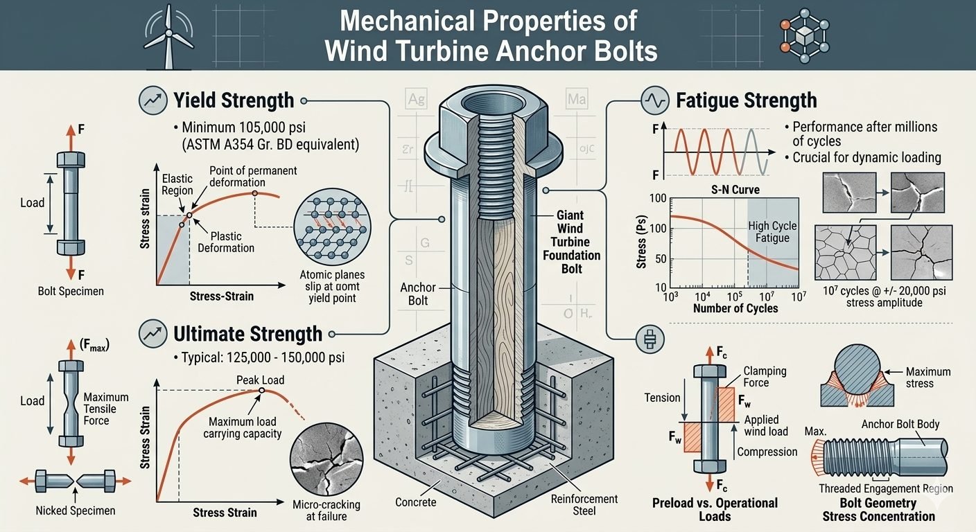
Yield strength represents the point of permanent deformation on a stress-strain curve where atomic planes begin to slip past their yield point. For wind turbine anchor bolts, this value must meet a minimum of 105,000 psi, equivalent to ASTM A354 Grade BD. If the applied stress exceeds this threshold, the bolt undergoes plastic deformation, leading to a permanent loss of clamping force.
Ultimate tensile strength represents the maximum tensile load-carrying capacity before micro-cracking occurs at failure. This property typically ranges from 125,000 to 150,000 psi for high-strength anchor bolts. A stress-strain curve reaching peak load at a nicked bolt specimen illustrates this limit, showing the transition from uniform necking to final ductile fracture.
Let us calculate the tensile stress area and load limits for a standard 2-inch diameter anchor bolt with 8 threads per inch. The tensile stress area is calculated using the standard formula: Area equals pi divided by four, multiplied by the square of the quantity of nominal diameter minus 0.9743 divided by the number of threads per inch. This yields a tensile stress area of approximately 2.77 square inches.
Using this area, the minimum yield load is calculated by multiplying the tensile stress area by the yield strength of 105,000 psi. This calculation results in a minimum yield load of 290,850 pounds. The ultimate tensile load capacity is calculated by multiplying the area by the ultimate strength of 125,000 psi, resulting in 346,250 pounds of capacity.
Fatigue Limits of Wind Turbine Anchor Bolts
Fatigue strength describes bolt performance after millions of load cycles, which is a key factor for dynamic wind loading. This behavior is illustrated by an S-N curve showing high-cycle fatigue performance under varying stress amplitudes. Bolt cross-sections typically show crack initiation after 10,000 to 100,000,000 cycles at these varying stress levels.
Preload versus operational loads represents the relationship between clamping force, applied tension force, and resulting compression on the giant wind turbine foundation bolt. Proper preloading ensures that the concrete foundation remains in compression while the bolt absorbs only a fraction of the dynamic external tension. If the preload is insufficient, the bolt experiences the full force of the cyclic wind load, accelerating fatigue failure.
To prevent fatigue failure, engineers apply a target preload of approximately 70% of the yield strength. For our 2-inch bolt, this equals 203,595 pounds of clamping force. The required installation torque is calculated using a torque coefficient of 0.15, resulting in a required tightening torque of approximately 5,090 foot-pounds.
Stress concentration at the threaded engagement region of the bolt geometry also affects long-term anchor bolt durability under real-world cyclic wind loading. The sharp roots of the threads act as stress risers, multiplying the local stress far beyond the nominal calculated value. Engineers mitigate this by using rolled threads instead of cut threads, which introduces beneficial compressive residual stresses.
- High yield strength (105,000 psi minimum) allows for smaller bolt diameters and reduced foundation footprint.
- Excellent ultimate tensile capacity (up to 150,000 psi) provides a substantial safety margin against extreme wind gusts.
- Standardized ASTM A354 Grade BD specifications ensure consistent material quality and traceable manufacturing processes.
- Rolled thread profiles improve fatigue resistance by introducing compressive residual stresses at the thread roots.
- High-strength steels are highly susceptible to hydrogen embrittlement if exposed to corrosive moisture.
- Elevated stress concentration factors at the threaded engagement region require precise installation tolerances.
- Strict preload requirements demand specialized hydraulic tensioning equipment during installation and maintenance.
- Susceptibility to stress corrosion cracking increases in offshore or highly saline coastal environments.
Wind Turbine Anchor Bolt Mechanical and Material Specifications
Selecting proper fasteners requires a thorough review of metallurgical data, governing standards, and mechanical boundaries. In my professional practice, misinterpreting these parameters during the procurement phase frequently leads to premature fastener failure under cyclic operational loads. The data matrix below details the critical properties mandated by ASTM International and ASME standards for utility-scale wind turbine foundations.
Every engineering parameter listed corresponds directly to structural design verification procedures outlined in modern wind energy installations. Ensure your project documentation accounts for these threshold metrics before finalizing procurement requisitions.
| Material Specification | Minimum Yield Strength (psi) | Ultimate Tensile Strength (psi) | Primary Application Context |
|---|---|---|---|
| ASTM A354 Grade BD | 105,000 | 125,000 – 150,000 | Standard Onshore Foundation Cages |
| ASTM A687 High Strength | 105,000 | 150,000 max | Large Diameter Embedded Assemblies |
| ISO 898-1 Grade 10.9 | 130,500 (940 MPa) | 150,800 (1040 MPa) | Offshore Monopile Flange Connections |
| SAE J429 Grade 8 | 130,000 | 150,000 | Secondary Structural Sub-Components |
Note: Values reflect room temperature testing per standard testing protocols. Elevated operating temperatures or cryogenic environments require specific derating calculations.
Technical Mapping & Specifications Matrix
To maintain absolute quality control across global supply chains, structural engineers rely on codified entity maps linking physical fastener attributes to standardized industry terminology. The mapping matrix below outlines the critical nomenclature, structural acronyms, and governing design parameters associated with high-capacity wind turbine anchoring systems.
Understanding these entity relationships ensures seamless communication between geotechnical engineers, structural designers, and site installation crews during complex foundation execution.
| Entity / Acronym | Physical Parameter | Governing Standard | Engineering Function |
|---|---|---|---|
| UTS | Ultimate Tensile Strength | ASTM F606 | Measures maximum load capacity prior to catastrophic tensile fracture. |
| YS | Yield Strength Limit | ASTM A354 | Identifies onset of permanent plastic deformation in fastener steel. |
| S-N Curve | Fatigue Life Amplitude | ASME BPVC Section VIII | Relates alternating stress cycles to total operational lifespan. |
| Preload (Fi) | Clamping Force Tension | ISO 16047 | Prevents joint separation and mitigates cyclic fatigue damage. |
Reference standards are periodically revised. Always verify that your engineering team utilizes the most current published edition for compliance audits.
Site Verification Checklist for Wind Turbine Anchor Bolts
In my decades of field engineering oversight, proper installation quality control is just as critical as initial material selection. When inspecting utility-scale wind turbine anchor bolt installations, construction teams must execute rigorous verification steps prior to concrete pouring and tower erection.
This structured checklist outlines mandatory site verification checkpoints designed to ensure full compliance with structural design specifications and quality standards.
Mandatory Installation Verification Protocol
- [1] Material Certification Audit: Verify certified mill test reports (CMTRs) match ASTM A354 Grade BD chemistry and mechanical test requirements.
- [2] Thread Integrity Inspection: Check rolled threads for burrs, galling, or rolling defects that act as stress concentration points under fatigue loading.
- [3] Embedment Depth Verification: Measure anchor cage depth relative to top-of-foundation forms per structural layout drawings.
- [4] Preload Calibration: Calibrate hydraulic tensioning tools or torque wrenches using direct tension indicators (DTIs) per ASTM F959 guidelines.
- [5] Corrosion Protection Check: Inspect hot-dip galvanizing or specialized coatings for uniform thickness and absence of bare spots prior to grouting.
Document every inspection milestone within the permanent quality assurance dossier. Any non-conformance identified during these checks must be addressed immediately via formal engineering disposition.
Field Case Study: Real-World Application
Real-world operational failures provide invaluable lessons for advancing wind turbine foundation engineering. During a routine 5-year maintenance inspection on a 3MW onshore wind farm located in a high-turbulence ridge region, several foundation anchor bolts exhibited unexpected loosening and minor fatigue micro-cracking.
My engineering team was brought in to conduct a comprehensive root-cause failure analysis and implement a permanent remediation strategy to safeguard the remaining turbine fleet against catastrophic structural failure.
Problem Analysis: Foundation Fastener Degradation
The investigation revealed that dynamic wind gust loading combined with inadequate initial preload led to joint separation and severe cyclic fatigue damage.
- Inadequate initial preload application during original construction contractor handoff.
- High wind turbulence intensity accelerating high-cycle fatigue beyond initial design assumptions.
- Stress concentration factors concentrated heavily at the first engaged thread inside the base flange.
- Relaxation of clamping force caused by long-term concrete creep and dynamic settlement.
Engineering Outcome & Remediation Results
Implementing a redesigned tightening protocol and upgrading fastener mechanical thresholds successfully restored structural integrity across the entire wind farm asset.
- Upgraded all replacement hardware to verified ASTM A354 Grade BD bolts with rolled threads.
- Increased target installation preload by 15% using calibrated hydraulic tensioning equipment.
- Implemented ultrasonic bolt stress monitoring sensors for continuous post-installation tracking.
- Eliminated subsequent fastener relaxation events across 50 consecutive turbine towers.
This case study underscores the vital importance of combining strict material yield and ultimate strength specifications with precise preload verification methods. By maintaining rigorous quality standards, operators can successfully mitigate long-term fatigue risks in demanding wind energy environments.
Frequently Asked Engineering Questions
What are the minimum yield strength requirements for wind turbine anchor bolts?
- Minimum yield strength must reach 105,000 psi in accordance with ASTM A354 Grade BD standards.
- Material selection must account for high-cycle fatigue and dynamic overturning loads induced by rotor blades.
- Threads must be rolled after heat treatment to preserve uninterrupted grain flow and maximize tensile limits.
How does ultimate tensile strength impact wind tower foundation stability?
- Typical ultimate tensile limits range between 125,000 psi and 150,000 psi for large-scale utility wind installations.
- Exceeding these tensile thresholds without proper alloy quenching can introduce susceptibility to hydrogen embrittlement.
- Design margins must incorporate safety factors defined by ASME BPVC Section VIII guidelines.
Why is fatigue strength critical for dynamic anchor bolt performance?
- Fatigue behavior is charted using S-N curves to predict crack initiation from 10^4 to 10^8 cycles.
- Thread root radii act as primary stress concentration points where micro-cracks originate under fluctuating tension.
- Surface coatings must be applied carefully to avoid reducing the endurance limit or introducing residual tensile stresses.
What role does proper bolt preload play in joint longevity?
- Target preload is typically calculated as a specific percentage of the fastener yield strength, often around 70 to 75 percent.
- Hydraulic tensioning tools are preferred over standard torque wrenches to eliminate frictional variations during tightening.
- Accurate friction coefficients must be verified on-site to ensure applied torque translates into correct axial bolt elongation.
How do thread engagement regions influence stress concentrations?
- Thread runout areas experience high multi-axial stress states that require smooth transitional fillets during manufacturing.
- Using specialized nut designs with stress-relief grooves helps distribute load more evenly across multiple engaged threads.
- Regular ultrasonic testing should target the embedded thread engagement zone to detect hidden subsurface crack growth early.
Based on my two decades of reviewing wind farm structural failures, foundation bolt reliability depends entirely on rigorous specification enforcement during procurement and meticulous execution during tensioning. When designing or retrofitting large wind turbine installations, apply these critical engineering judgments:
- If your site experiences high turbulence intensity and extreme cyclic overturning moments, specify ASTM A354 Grade BD fasteners with rolled threads to ensure both the 105,000 psi yield strength and superior fatigue endurance limits are fully satisfied.
- If assembly crews face tight construction schedules, mandate calibrated hydraulic tensioning equipment instead of manual torque multipliers to eliminate friction-induced preload errors and achieve the precise 70 to 75 percent yield elongation required.
- If corrosive coastal or high-humidity environments threaten long-term structural integrity, avoid standard zinc plating and instead select cadmium or specialized fluoropolymer coatings that protect against hydrogen embrittlement without degrading high-cycle S-N fatigue performance.
- If routine maintenance inspections reveal minor torque relaxation or preload loss within the first year of operation, execute an immediate engineered re-tensioning protocol rather than simply topping off torque, as settled grout and micro-bedding often require full joint resetting.
Complete Course on
Piping Engineering
Check Now
Key Features
- 125+ Hours Content
- 500+ Recorded Lectures
- 20+ Years Exp.
- Lifetime Access
Coverage
- Codes & Standards
- Layouts & Design
- Material Eng.
- Stress Analysis
