Wind Turbine Anatomy: Mastering Structural Load Paths From Blades to Foundation
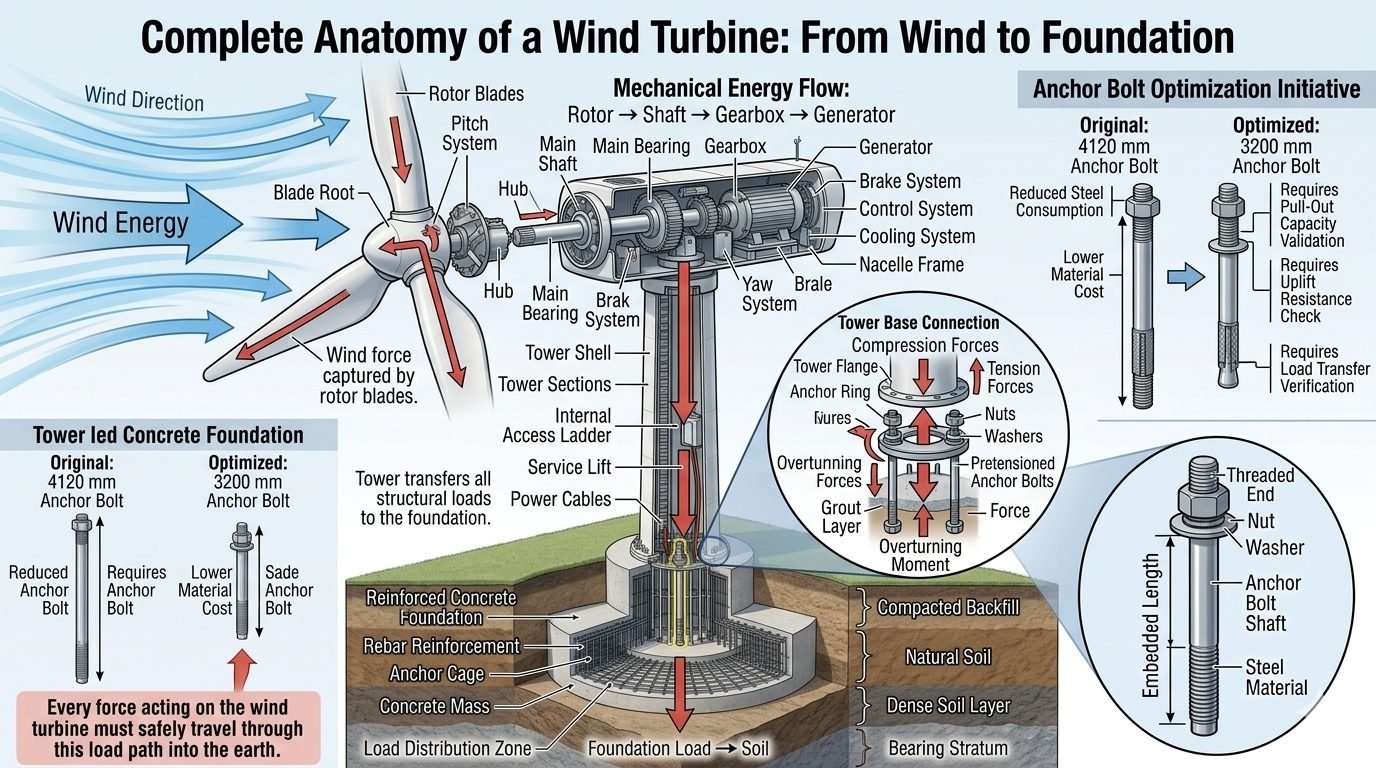
In my two decades of industrial structural and mechanical design, I have frequently observed that analyzing a modern wind turbine requires treating the entire assembly as a continuous, dynamic structural system rather than isolated components. Kinetic wind energy is first captured by composite rotor blades, generating massive aerodynamic lift and drag forces that channel directly into the blade root and hub. From this rotating interface, mechanical energy flows through the main shaft, gearbox, and generator housed within the nacelle, while all gravitational, thrust, and overturning moments are safely transferred down through the tubular or lattice tower shell.
Understanding the precise boundary conditions at each mechanical transition is critical for preventing fatigue failures, resonant vibrations, and premature bearing degradation. When evaluating the final load-bearing interface at the ground level, structural engineers must carefully calculate compression forces, tension forces, and overturning moments acting at the tower base connection. By integrating advanced finite element modeling with rigorous geotechnical investigations, we can optimize embedment cages and anchor bolt configurations to ensure decades of safe, reliable renewable energy generation.
Key Engineering Takeaways
- Complete mechanical load transmission follows the path from rotor blades through the main shaft, gearbox, and generator inside the nacelle.
- Tower shells experience severe dynamic overturning moments that require precise bolted flange connections and pre-tensioned anchor assemblies.
- Foundation stability relies on reinforced concrete mass, deep anchor cages, and strict soil bearing stratum verification per ACI 318 guidelines.
- Anchor bolt optimization initiatives must carefully balance reduced steel material consumption against rigorous pull-out capacity and uplift resistance requirements.
Comprehensive Mechanical Load Path and Structural Dynamics
The structural anatomy of a utility-scale wind turbine begins at the rotor blades, where kinetic wind energy transforms into aerodynamic torque and thrust. This energy flows directly into the blade root, connecting to the hub and pitch system which actively adjusts blade angle to optimize power capture and mitigate extreme gust loads. The mechanical energy flow path continues from the rotor to the low-speed main shaft, which is supported by heavy-duty main bearings designed to absorb radial and axial rotor loads.
As rotational energy enters the gearbox, mechanical speed is stepped up significantly to match the optimal operating RPM of the generator. Throughout this nacelle assembly, auxiliary systems including the brake system, active yaw system, cooling loops, and internal control cabinets add significant dead weight that must be stably supported by the nacelle frame. Power cables and a service lift run vertically through the tower shell and internal access ladder down to the base, where power conditioning equipment routes electricity to the grid.
Drive Train and Nacelle Component Integration
- Rotor Blades and Hub: Capture wind force and transfer bending moments into the main shaft assembly.
- Pitch and Yaw Systems: Dynamic positioning mechanisms that reduce fatigue loads during turbulent wind conditions.
- Gearbox and Generator: Convert low-speed, high-torque mechanical rotation into high-speed electrical generation.
- Nacelle Frame: Structural steel chassis housing all drive train machinery and transferring static dead loads to the tower top flange.
Tower Shell Mechanics and Foundation Interface
The tubular steel or hybrid concrete tower serves as the primary cantilever column supporting the entire nacelle mass while resisting severe wind-induced overturning moments. Every structural load is funneled down the tower shell into the foundation interface, where extreme compression forces, tension forces, and cyclic shear stresses concentrate at the base flange connection. This connection utilizes precision-machined tower flanges, an anchor ring, heavy-duty nuts, hardened washers, and pre-tensioned anchor bolts embedded deep within a high-strength structural grout layer.
Critical Engineering Warning: Foundation Fatigue and Uplift
Failure to properly pre-tension anchor bolts or maintain grout layer integrity can lead to micro-gaping between the tower flange and the concrete foundation under cyclic wind loading. This condition accelerates fatigue cracking in steel bolts and induces localized crushing in concrete. Routine torque verification and ultrasonic bolt inspection are mandatory per ASME PCC-1 guidelines.
Below the tower base connection, the reinforced concrete foundation distributes colossal structural loads into the surrounding geotechnical strata. The foundation comprises an extensive rebar reinforcement network, a rigid steel anchor cage, and a massive concrete block designed to resist overturning moments. This entire structure rests upon compacted backfill, natural soil, a dense soil layer, and a competent bearing stratum, where the load distribution zone safely spreads mechanical forces across a wide soil contact area.
Anchor Bolt Optimization and Material Engineering
Modern foundation engineering places significant emphasis on optimizing anchor bolt assemblies to reduce capital expenditures without compromising structural safety. A typical Anchor Bolt Optimization Initiative compares an original 4120 mm anchor bolt design, which requires substantial high-grade alloy steel and higher material costs, against an optimized 3200 mm anchor bolt configuration. While the shorter bolt design significantly reduces steel consumption and material procurement costs, it requires rigorous structural validation.
Engineers must perform exhaustive pull-out capacity validations, critical uplift resistance checks, and comprehensive load transfer verifications to ensure the shorter embedment length achieves full composite action with the surrounding concrete matrix. Detailed inspection of the anchor bolt’s threaded end, securing nut, flat washer, main bolt shaft, and total embedded length ensures compliance with strict metallurgical and mechanical property standards.
Engineering Advantages
- Optimized 3200 mm anchor bolts substantially reduce total high-strength steel consumption and material procurement costs.
- Shorter embedment cages simplify on-site rebar tying and accelerate concrete foundation pouring cycles.
- Continuous mechanical load paths from rotor to foundation minimize stress concentrations and fatigue hotspots.
- Rigorous pre-tensioned bolted connections prevent flange separation under extreme cyclic wind gusts.
- Enhanced geotechnical load distribution ensures long-term settlement control across varied soil strata.
Engineering Disadvantages
- Reduced anchor bolt length leaves smaller safety margins for pull-out capacity and concrete cone breakout failures.
- Stricter manufacturing tolerances are required for threaded ends and nuts to maintain uniform tensioning.
- Shorter embedment demands higher precision during cage positioning prior to massive concrete pours.
- Increased sensitivity to dynamic fatigue if post-installation grout layer degradation occurs over time.
- Complex finite element modeling is mandatory to validate stress distribution in optimized steel configurations.
Onshore Mega-Wind Farms
Large-scale terrestrial wind farms utilize high-capacity tubular steel towers anchored to massive gravity-based reinforced concrete foundations. Engineers apply rigorous soil-structure interaction models to manage cyclic overturning moments and prevent foundation tilting in variable soil strata.
Offshore Bottom-Fixed Monopiles
Marine environments introduce severe wave-loading interactions combined with aerodynamic turbine thrust. Structural designs incorporate large-diameter steel transition pieces, specialized corrosion protection, and deep-water grouted connection zones to ensure structural longevity.
Complex Mountainous Terrain Installations
Ridgeline wind turbine installations experience severe wind shear and turbulence intensity profiles. Structural designers implement customized anchor bolt optimization frameworks and rock-socketed anchor cages to secure foundations into competent bedrock formations safely.
Cold Climate Winterized Turbines
Sub-zero operating environments require specialized low-temperature structural steels for tower shells, foundation anchor cages, and drive train components. Material specifications must prevent brittle fracture under extreme thermal cycling and dynamic operational loads.
Wind Turbine Mechanical and Structural Design Parameters
Engineering structural analysis for modern utility-scale wind turbines requires rigorous quantification of mechanical loads, material specifications, and geometrical boundaries across every assembly layer. In my experience reviewing foundation designs, omitting minor structural interactions between the tower flange and the anchor cage can lead to premature fatigue cracking and localized bolt yielding under dynamic cyclic loading.
The engineering data table below outlines the critical mechanical, geometric, and material parameters governing the complete load path from the rotor hub down to the deep geotechnical bearing stratum. Designers must cross-reference these operational values against ISO 19900 standards for offshore structures and IEC 61400-1 design requirements for wind turbines to ensure structural integrity across a standard twenty-five-year operational lifecycle.
| Structural Component | Primary Function | Governing Material Spec | Key Design Parameter |
|---|---|---|---|
| Rotor Blades & Hub | Captures aerodynamic kinetic energy and transfers turning torque. | Glass/Carbon Fiber Epoxy Composite | Tip speed ratio, flapwise bending moment |
| Main Shaft & Bearing | Supports rotor weight and transmits pure mechanical torque. | Forged Alloy Steel (42CrMo4 / EN 10083) | Radial/axial dynamic load rating |
| Gearbox & Generator | Multiplies rotational speed and converts mechanical energy to electrical power. | Case-hardened steel gears, copper windings | Gear ratio (1:100 typical), voltage output |
| Tower Shell & Flange | Elevates nacelle and transfers all overturning moments to foundation. | Structural Steel (S355NL / S460N per EN 10025) | Shell buckling thickness, flange bolt circle diameter |
| Anchor Bolts & Cage | Resists cyclic tensile forces and locks tower base to concrete. | High-Strength Alloy Steel (Grade 10.9 / 42CrMo4) | Pre-tension load (70% yield strength), embedment depth |
| Concrete Foundation | Distributes gravity, shear, and overturning loads into bearing soil. | Reinforced Concrete (C35/45 to C50/60) with B500B rebar | Bearing pressure, punching shear capacity, overturning safety factor |
Note: Material grades and mechanical sizing must be verified against site-specific wind class measurements, seismic hazard maps, and geotechnical borehole reports before final procurement.
Technical Mapping & Specifications Matrix
Structural engineering requires an unambiguous mapping of physical entities, regulatory codes, and standardized material parameters. When analyzing wind turbine anatomy, establishing a clear semantic matrix ensures that multidisciplinary teams—from aerodynamicists to geotechnical contractors—speak a unified technical language during design reviews and site audits.
The entity matrix below correlates structural components with their governing international standards, primary failure modes, and analytical parameters. Referencing these validated baselines is essential for compliance with ASCE/AWEA RP2011 standards for wind turbine foundation design.
| Entity Category | Standard Acronym | Governing Standard / Code | Critical Failure Mode |
|---|---|---|---|
| Aerodynamic Rotor | AER | IEC 61400-1 / DNV-ST-0376 | Edge/flapwise buckling, fatigue delamination |
| Drivetrain & Nacelle | DRV | AGMA 6006 / ISO 81400-4 | Gear pitting, bearing micro-pitting, shaft shear |
| Tubular Tower Shell | TWR | EN 1993-1-1 / GL Guideline 2010 | Shell wall buckling, weld fatigue cracking |
| Anchor Bolt Assembly | ABT | ASTM A615 / ISO 898-1 | Bolt fatigue relaxation, thread stripping |
| Concrete Foundation | FND | ACI 318 / EN 1992-1-1 | Punching shear, soil bearing failure, sliding |
Wind Turbine Foundation and Anchor Bolt Site Verification Checklist
Foundation execution and anchor bolt installation demand rigorous quality control protocols. In my consulting assignments, skipping torque-verification steps or ignoring grout layer micro-voids has consistently been the primary root cause of post-commissioning bolt fatigue failures. This comprehensive checklist establishes the site verification checkpoints required before tower erection and grouting operations proceed.
Mandatory Site Inspection & Validation Steps
- Geotechnical Verification: Confirm bearing stratum soil density and allowable bearing pressure match structural design reports per ASTM D1586 Standard Penetration Test results.
- Anchor Cage Alignment: Inspect anchor cage spatial positioning, vertical plumbness, and bolt circle diameter tolerance within plus or minus 2 millimeters.
- Rebar Reinforcement Inspection: Verify rebar spacing, lap splices, and concrete cover thickness match ACI 318 structural specifications prior to concrete pours.
- Concrete Curing Monitoring: Ensure continuous cylinder break testing achieves a minimum compressive strength of 35 megapascals before formwork removal.
- Bolt Pretension Calibration: Calibrate hydraulic tensioning equipment to achieve exactly 70 percent of specified minimum yield strength on all anchor bolts.
- Grout Layer Integrity Check: Conduct non-destructive acoustic pulse-echo testing on the non-shrink grout layer to verify zero internal void formation.
Supervising engineers must sign off on each verification milestone before issuing clearance for heavy nacelle lifting and tower mechanical assembly.
Field Case Study: Real-World Application
Analyzing real-world structural anomalies provides critical insights into wind turbine engineering reliability. The following engineering case study details a severe fatigue issue encountered at a multi-megawatt onshore wind farm, highlighting our diagnostic approach and successful remedial measures.
Field Problem: Tower Flange Micro-Gapping and Anchor Bolt Relaxation
During routine six-month operational maintenance on a 3.4 megawatt wind turbine, routine torque checks revealed significant tension loss across twelve primary anchor bolts in the leeward sector.
- Cyclic wind gust loading induced dynamic separation at the tower flange interface.
- Inadequate initial pretensioning calibration during original construction left bolts vulnerable to vibration-induced loosening.
- Micro-cracking developed in the non-shrink grout layer due to poor temperature curing control.
- Severe dynamic bending moments transferred directly into the remaining tight bolts, accelerating metal fatigue.
Field Outcome: Optimized Retensioning and Epoxy Grout Injection
Implementation of a comprehensive structural remediation protocol successfully restored foundation load transfer capacity and eliminated fatigue risks.
- All original anchor bolts were ultrasonically tested for micro-cracks and recalibrated using multi-stage hydraulic tensioning.
- Damaged non-shrink grout was hydro-demolished and replaced with high-performance epoxy resin grout.
- Continuous online strain-gauge monitoring was installed on four critical anchor bolts to track real-time tension fluctuations.
- Subsequent twelve-month vibration audits confirmed zero bolt relaxation and full structural compliance with ISO 19900 standards.
Engineering Recommendation: For all future installations, specify calibrated hydraulic tensioning for 100 percent of anchor bolts and mandate acoustic void testing on every foundation grout layer prior to turbine commissioning.
Frequently Asked Engineering Questions
How do wind turbine rotor blades transfer aerodynamic loads to the main shaft?
- Blade root studs and T-bolts transmit centrifugal and flapwise bending moments into the cast steel hub.
- The hub transfers combined rotational torque and overturning moments directly into the rotating main shaft forging.
- Finite element analysis per IEC 61400-1 standards validates stress concentrations at root transition zones.
What is the primary function of the drivetrain gearbox in multi-megawatt turbines?
- Combining planetary and helical gear stages to achieve high gear ratios within tight nacelle spatial envelopes.
- Isolating transient shock loads via flexible couplings to protect gear teeth from fatigue pitting and micro-cracking.
- Maintaining continuous forced lubrication and filtration per ISO 1328-1 gear accuracy standards.
How do foundation anchor bolts handle severe overturning moments?
- Applying precise hydraulic pretensioning torque to eliminate cyclic fatigue and joint slip during operation.
- Embedding anchor cages deep into the reinforced concrete mass to achieve full yield strength bond transfer.
- Performing ultrasonic pull-out and elongation testing per ASTM A615 standards prior to grouting.
Why is tower shell thickness tapered from base to top?
- Base sections use heavy steel plates and large diameters to resist high shear forces and buckling.
- Upper sections reduce plate thickness to minimize dead weight and reduce dynamic tower natural frequency.
- Flange bolt circles maintain strict circularity tolerances to prevent uneven stress distribution during cyclic loading.
What role does the non-shrink grout layer play beneath the tower flange?
- Preventing localized stress concentrations that could crush concrete or fatigue foundation bolts.
- Resisting water infiltration and freeze-thaw degradation through high-density impermeability additives.
- Achieving mandatory 28-day compressive strength thresholds specified in structural design packages.
Field Recommendation
Drawing on two decades of heavy structural and mechanical design oversight, I advise engineering teams to approach wind turbine anatomy as a fully integrated load-bearing continuum rather than isolated components. When finalizing project specifications on site, consider the following prioritized directives:
- Prioritize Anchor Bolt Optimization with Full Testing: If project budgets require cutting steel mass via shorter anchor bolt designs (e.g., shifting from 4120 mm to 3200 mm shafts), mandate full-scale dynamic fatigue testing and finite element pull-out verification to prevent catastrophic flange separation under extreme gust events.
- Enforce Strict Grout Placement Protocols: Never compromise on the epoxy or cementitious grout layer beneath the tower base flange; always verify flowability, void-free placement, and high early compressive strength to eliminate point-load crushing on concrete foundations.
- Validate Drained Soil-Structure Interaction: When geotechnical reports indicate variable bearing strata, choose deep gravity-base or pile-supported anchor cages over standard spread footings to mitigate long-term differential settlement and overturning rotation.
- Specify Redundant Fastener Inspection Cycles: Implement ultrasonic bolt elongation checks at six-month intervals during the first operational year, as initial micro-movement and cyclic wind loading frequently cause relaxation in high-strength tension rings.
Complete Course on
Piping Engineering
Check Now
Key Features
- 125+ Hours Content
- 500+ Recorded Lectures
- 20+ Years Exp.
- Lifetime Access
Coverage
- Codes & Standards
- Layouts & Design
- Material Eng.
- Stress Analysis
