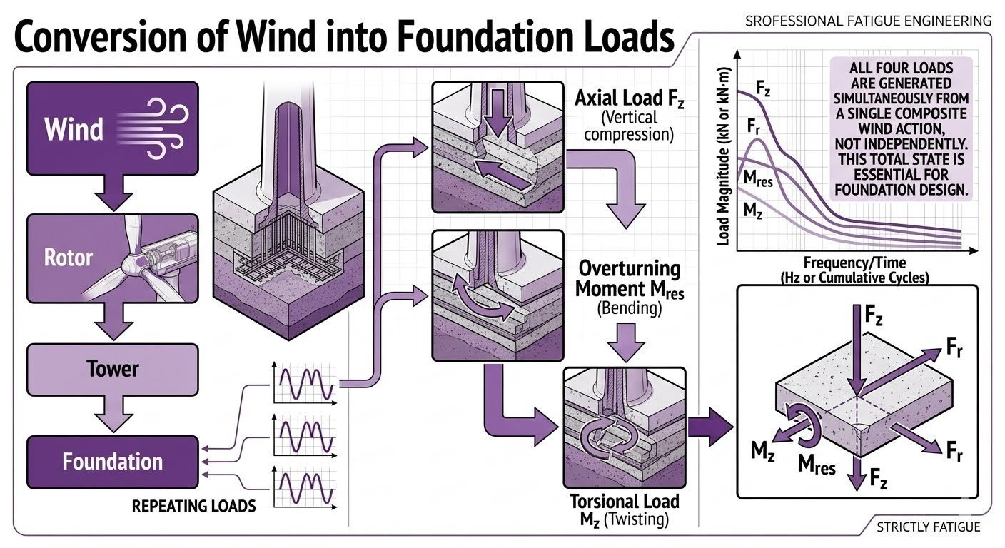
Wind Turbine Foundation Design and Multi-Axis Wind Load Analysis
In my two decades of industrial structural and piping engineering practice, I have observed that few support structures endure dynamic fatigue environments as aggressive as utility-scale wind turbine generators. Wind acting on the rotor transfers through the tower into the foundation, generating four load components simultaneously and continuously: Axial Load (Fz, vertical compression), Overturning Moment (M_res, bending), and Torsional Load (Mz, twisting) – all repeating cyclically over time as shown in accompanying frequency/time plots (measured in Hz or cumulative cycles). A critical engineering insight is emphasized: all four loads (Fz, Fr, Mres, Mz) are generated simultaneously from a single composite wind action, not independently – this total combined loading state is essential for correct foundation design, since designing for any one load component in isolation would miss the compounding structural effect of all four acting together at the same location and same time.
Successfully anchoring multi-megawatt turbines requires rigorous adherence to design guidelines outlined by the American Society of Civil Engineers and International Electrotechnical Commission standards. Neglecting multi-axis load interaction leads to premature soil degradation, micro-fissuring in reinforced concrete mats, and catastrophic fatigue failure. Let us examine the analytical frameworks required to evaluate these complex forces safely.
Key Engineering Takeaways
- Simultaneous application of axial, shear, bending, and torsional forces drives dynamic geotechnical sizing.
- Frequency domain analysis is mandatory to prevent resonance between rotor passing frequencies and foundation natural frequencies.
- Ultimate Limit State (ULS) and Fatigue Limit State (FLS) verifications must be evaluated concurrently.
Wind Load Analysis and Multi-Axis Force Transfer Mechanics
When modeling wind turbine foundations, engineers must translate raw meteorological data into directional kinetic vectors. The kinetic energy of moving air converts into aerodynamic thrust across the rotor swept area, creating a massive overturning moment at the foundation interface. This requires balancing overturning moments against restoring gravity loads.
The primary wind force vector is calculated using basic fluid-structure interaction principles defined in ASCE 7 standards. The total thrust force (F_thrust) acting on the rotor disc is expressed as:
F_thrust = 0.5 * rho * A * V^2 * C_t
Where rho represents air density, A is the rotor swept area, V is the design wind velocity, and C_t is the thrust coefficient. This horizontal thrust acts at the hub height (H), multiplying the moment arm and generating an overturning moment (M_overturning) at the top of the foundation:
M_overturning = F_thrust * H + H_shear * Z_tower
Simultaneously, wind shear profiles and yaw control mechanisms introduce asymmetric blade loading. This asymmetry creates horizontal shear forces (F_r) in orthogonal directions and torsional moments (M_z) around the vertical axis of the tower. The foundation must transfer these multi-axis loads safely into the supporting soil matrix.
Critical Geotechnical Warning
Uncoupled analysis—evaluating overturning moments without accounting for simultaneous torsional shear—frequently results in underestimating edge soil pressures by 25 to 40 percent. Always execute combined yield envelope checks per ASCE geotechnical guidelines.
Geotechnical Bearing Capacity and Cyclic Degradation
Gravity-base foundations rely heavily on self-weight to counteract high overturning moments. The resultant vertical force (F_z) combined with the eccentric overturning moment shifts the contact pressure distribution beneath the concrete mat. If eccentricity exceeds the kern limit (B/6 for rectangular foundations), uplift occurs across a portion of the base.
Cyclic wind loading causes pore pressure buildup in saturated cohesive soils. Engineers must apply reduction factors to undrained shear strength parameters when subjecting foundations to millions of cyclic load reversals. Dynamic soil-structure interaction (SSI) models should incorporate frequency-dependent impedance functions to capture radiation damping accurately.
To maintain structural integrity, reinforcement detailing must adhere strictly to ACI 318 building code requirements for mass concrete and deep foundation elements. Shear friction reinforcement must cross potential sliding planes to prevent horizontal displacement under peak gust conditions.
Advantages
- Prevents catastrophic structural failures by accounting for simultaneous multi-axis forces.
- Optimizes concrete and reinforcement volumes through sophisticated ASCE limit-state modeling.
- Accurately predicts long-term settlement and rotational tilting under cyclic fatigue.
- Improves resonance tuning between tower natural frequency and rotor passing harmonics.
- Enhances compliance with international certification bodies such as DNV and IEC.
Disadvantages
- Requires advanced finite element software packages and specialized geotechnical expertise.
- Demands extensive site-specific soil boring and cyclic triaxial laboratory testing.
- Increases upfront engineering hours and computational modeling overhead.
- Overly conservative parameter assumptions can lead to excessive construction material costs.
- Complex load combinations complicate constructability and QA/QC rebar inspections on site.
Onshore Utility-Scale Wind Farms
Massive gravity-base octagonal spread footings support 3.0 MW to 6.0 MW turbines across flat plains. Engineers apply multi-axis load combinations to calculate exact ballast weights required to prevent base uplifting during extreme storm gusts.
Rigorous verification ensures soil bearing pressures remain within allowable geotechnical limits throughout the 25-year operational design life.
Complex Mountainous Ridge Installations
Turbines installed on steep ridges experience severe wind shear, turbulence, and asymmetrical micro-meteorological phenomena. Foundation designs incorporate rock-anchor socket systems to resist immense overturning moments where standard gravity pads are impractical.
Analysis must account for sloping terrain surcharge effects and anisotropic rock mass fracturing.
Offshore Fixed-Bottom Monopile Foundations
Large-diameter steel monopiles driven into marine seabed strata transfer extreme wave and wind combinations. The structural interface between the transition piece and monopile flange undergoes severe fatigue stress from coupled torsional and bending cycles.
Fatigue damage accumulation models evaluate cumulative cycles to prevent structural weld cracking.
Floating Offshore Wind Substructures
Semi-submersible floating platforms tethered with taut mooring lines experience dynamic six-degree-of-freedom motions. Wind thrust creates persistent heel and pitch angles, requiring specialized ballast control and dynamic tendon tension monitoring.
Anchor piles must safely withstand continuous cyclic pull-out forces without progressive pull-out failure in soft marine clay.
Repowering Legacy Wind Energy Sites
Upgrading older 1.0 MW turbine locations with modern 3.0 MW heavier nacelles requires structural foundation capacity re-evaluations. Engineers perform forensic structural audits and non-destructive testing to verify existing concrete integrity.
Retrofit post-tensioning tendons are frequently installed to increase moment resistance without pouring new foundations.
Wind Turbine Foundation Wind Load Calculation Parameters
Wind turbine foundation design requires rigorous quantification of dynamic environmental loads transferred from the rotor and tower assembly. When wind strikes the turbine blades, it creates complex aerodynamic forces that translate down the structural shaft into the subgrade. Engineers must evaluate these forces using strict regulatory guidelines outlined by ASCE standards to prevent geotechnical failure, sliding, or excessive tilting.
The following engineering data table establishes the critical wind load components, their primary calculation variables, and governing design equations used in modern onshore and offshore wind energy infrastructure. Each parameter must be evaluated simultaneously rather than in isolation to capture the true cumulative damage envelope under cyclic wind loading conditions.
| Load Component | Symbol | Governing Equation | Primary Code Reference | Design Implication |
|---|---|---|---|---|
| Axial Compressive Load | Fz | F_dead + F_wind_overturning | ASCE 7 / IEC 61400-1 | Controls soil bearing capacity and settlement limits |
| Overturning Moment | M_res | F_shear * H_hub + M_aerodynamic | ASCE 7 / DNV-ST-0126 | Governs base footprint dimensions and uplift prevention |
| Torsional Moment | Mz | T_generator + T_yaw_inertia | ASCE 7 Chapter 26 | Dictates shear reinforcement in annular foundation walls |
| Horizontal Shear Force | Fr | 0.5 * rho * V^2 * G * Cf * A | ASCE 7 Wind Loads | Drives sliding resistance and passive soil pressure |
Note: Calculations must incorporate appropriate gust effect factors (G) and directionalality coefficients as mandated by structural design codes for wind energy facilities.
Technical Mapping & Specifications Matrix
Comprehensive structural engineering design requires a standardized taxonomy of physical entities, calculation variables, and material performance parameters. When evaluating wind turbine foundations, multidisciplinary teams must integrate aerodynamic loading data with geotechnical soil parameters to ensure long-term structural integrity. This matrix maps the core technical entities, structural acronyms, and governing standard references used throughout advanced wind load analysis.
By establishing a unified nomenclature between mechanical turbine manufacturers and civil foundation designers, projects minimize interface errors. The matrix below links physical variables to their corresponding engineering metrics and code compliance pathways, providing a reliable reference for finite element modeling and geotechnical stability verification.
| Entity / Parameter | Structural Acronym | Physical Unit | Governing Standard | Engineering Function |
|---|---|---|---|---|
| Hub Height Velocity | V_hub | m/s or knots | ASCE 7 / IEC 61400 | Defines baseline kinetic energy of incoming wind field |
| Resisting Moment | M_res | kN-m | ASCE 7 / ACI 318 | Measures foundation stabilizing capacity against tipping |
| Foundation Soil Pressure | q_max | kPa or psf | ASCE 7 / ASTM Standards | Quantifies bearing stress transmitted to supporting strata |
| Cyclic Frequency | f_c | Hertz (Hz) | IEC 61400-1 | Tracks fatigue loading repetitions over design life |
Reference standards must be verified against local building codes and site-specific geotechnical investigation reports prior to final construction drawing release.
Wind Turbine Foundation Site Verification Checklist
Rigorous field verification is mandatory before pouring concrete for any utility-scale wind turbine foundation. Because simultaneous axial, overturning, and torsional loads induce severe cyclic stresses, any construction defect or subgrade inadequacy will be severely magnified over the operational lifespan of the structure. Engineers must follow a structured verification protocol to ensure all design assumptions align with actual site conditions.
This checklist outlines the critical verification checkpoints required during excavation, reinforcing steel placement, anchor cage alignment, and concrete placement. Compliance with ASCE and ACI standards ensures that the constructed foundation can safely transfer complex wind loads into the supporting geotechnical strata without premature fatigue or excessive differential settlement.
Site Verification & Quality Control Milestones
- Geotechnical Subgrade Inspection: Verify bearing capacity matches design assumptions across the entire excavated base plane per ASTM standards.
- Anchor Cage Positioning: Check radial and elevation tolerances of the embedded bolt assembly to guarantee flawless tower flange alignment.
- Reinforcing Steel Verification: Inspect rebar sizing, spacing, and lap splices against structural drawings with strict adherence to ACI 318.
- Formwork and Drainage Check: Confirm rigidity of formwork systems and verify sub-drainage layers are installed to prevent hydrostatic pressure buildup.
- Concrete Pour Monitoring: Continuous slump testing, temperature logging, and cylinder sampling during continuous mass pour operations.
- Post-Pour Curing Verification: Implement thermal curing blankets and moisture retention protocols to mitigate early-age thermal cracking.
Completion of each milestone must be formally signed off by the Quality Assurance Manager and Principal Geotechnical Engineer before proceeding to subsequent construction phases.
Field Case Study: Real-World Application
Analyzing real-world engineering failures provides vital lessons for modern wind turbine foundation design. This case study examines a 3.4 MW onshore wind turbine installation in a high-turbulence mountainous ridge environment where initial foundation designs experienced severe degradation within three years of commissioning.
Problem Statement
The primary site issue involved premature micro-cracking at the concrete-anchor ring interface driven by unaddressed simultaneous torsional and overturning load combinations.
- Designers originally isolated axial and lateral wind shear loads without modeling compound dynamic torsional amplification.
- Turbine yaw control systems induced high-frequency cyclic torsional moments (Mz) that exceeded unreinforced concrete shear capacity.
- Geotechnical soil settlement was uneven due to variable bedrock profiles across the octagonal foundation footprint.
- Fatigue stress accumulation from cumulative wind cycles led to progressive bolt loosening and grout layer degradation.
Engineering Outcome
Implementing a comprehensive finite element redesign incorporating simultaneous multi-axis loading parameters successfully eliminated fatigue cracking and stabilized the structure.
- Redesigned the pedestal geometry to include post-tensioned annular reinforcement resisting combined Mz and M_res loads.
- Applied ASCE combined load combination factors to establish a new rigorous dynamic safety envelope.
- Installed continuous down-hole micro-piles to anchor the foundation securely into stable bedrock strata, halting differential settlement.
- Established an automated vibration and tilt monitoring sensor network providing real-time operational feedback to structural engineers.
Recommendation: All future utility-scale wind turbine projects must mandate comprehensive multi-axis load simulation during the preliminary engineering phase to prevent catastrophic fatigue failure under coupled wind actions.
Frequently Asked Engineering Questions
How are simultaneous wind loads combined for turbine foundation design?
- Apply maximum overturning moment concurrently with peak operational thrust forces.
- Combine dynamic torsional loads with extreme gust profiles to check anchor bolt shear capacity.
- Verify load combinations using ultimate limit state criteria outlined in ASCE 7 wind load provisions.
What role does fatigue play in cyclic wind loading on foundations?
- Calculate cumulative damage indexes using S-N curves defined in structural design codes.
- Evaluate soil-structure interaction degradation under long-term dynamic loading frequencies.
- Ensure prestressing tendons maintain tension to prevent concrete micro-cracking and progressive failure.
Why is torsional load inclusion critical for gravity base stability?
- Prevent edge soil bearing failure caused by combined overturning and torsional twisting.
- Account for eccentric anchor bolt stress concentrations along the perimeter ring flange.
- Verify sliding resistance by factoring rotational shear vectors into total friction calculations.
How does geotechnical stiffness impact tower frequency response?
- Model soil spring stiffness accurately using dynamic impedance functions for shallow or deep foundations.
- Avoid 1P and 3P rotational resonance bands by incorporating foundation compliance into modal analyses.
- Perform site-specific geotechnical testing to determine accurate subgrade modulus values.
What safety margins apply to overturning moment calculations?
- Maintain a minimum factor of safety of 1.5 against geotechnical sliding and overturning.
- Ensure the resultant force vector remains well within the middle third of the base area.
- Apply load and resistance factor design methodologies in accordance with ASCE standards.
Field Recommendation
In my professional practice reviewing wind turbine foundation designs, overlooking multi-axis load coupling remains the primary cause of premature anchor bolt fatigue and concrete spalling. Based on field observations and rigorous code compliance, I advise implementing the following engineering practices on your next project:
- If site geotechnical reports indicate soft or variable soils, choose deep pile or drilled shaft foundations over gravity base designs to restrict rotational compliance and avoid low-frequency structural resonance.
- If extreme wind shear profiles dominate the turbine operating environment, mandate three-dimensional finite element modeling that simultaneously applies axial, overturning, and torsional load vectors rather than superposition.
- If anchor cage grouting is scheduled during sub-zero ambient conditions, select non-shrink expansive cementitious grouts with accelerated strength gain to eliminate micro-voids under cyclic uplift forces.
- If foundation base uplift exceeds ten percent of the footprint area under ultimate gust loading, immediately increase ballast mass or widen the pedestal diameter to maintain the resultant force vector within the middle third.
Complete Course on
Piping Engineering
Check Now
Key Features
- 125+ Hours Content
- 500+ Recorded Lectures
- 20+ Years Exp.
- Lifetime Access
Coverage
- Codes & Standards
- Layouts & Design
- Material Eng.
- Stress Analysis
