Vertical Downward Load Analysis for Structural Foundation Design
In my twenty years of piping and structural engineering practice, managing vertical downward loads (Fz) correctly remains the single most critical factor in preventing differential settlement and structural distress. When heavy process equipment, piping deadweights, and thermal bundle loads bear down on structural supports, the underlying soil must absorb and distribute these massive forces without exceeding its allowable bearing capacity. Throughout this guide, I will walk you through the rigorous mechanical principles and load-transfer mechanics governing foundation stress analysis.
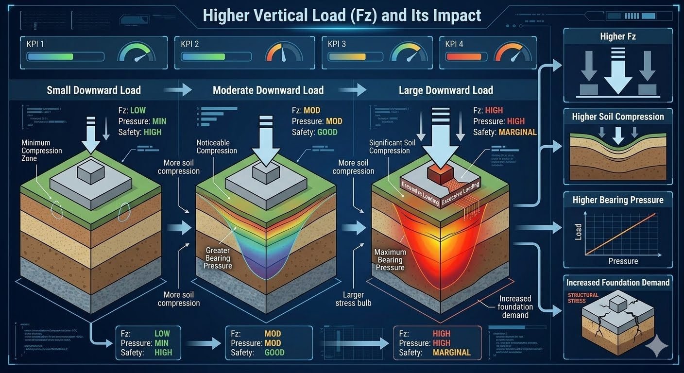
As Fz transitions from nominal operating conditions to extreme upset scenarios, the resulting stress bulb expands significantly within the geotechnical strata. Understanding this progression allows engineers to size concrete pedestals, reinforcement mats, and pile caps accurately in accordance with industry codes.
Key Engineering Takeaways
- Small vertical loads produce minimal soil compression and localized stress bulbs safely below allowable limits.
- Moderate loading increases bearing pressure proportionally, requiring careful verification of soil shear strength parameters.
- Large downward loads push foundations toward marginal safety factors, triggering mandatory load-versus-pressure curve reassessments.
- Downstream foundation demand scales directly with Fz increments, driving heavier structural reinforcement specifications.
Vertical Downward Load Mechanics and Soil Bearing Stress Analysis
Analyzing vertical downward load (Fz) requires a structured approach that links equipment deadweight, operating fluids, and external reactions to geotechnical responses. When Fz is small, the soil experiences minimal elastic deformation, and the resultant stress bulb remains shallow. In this baseline stage, safety factors are high, and foundation demand is governed primarily by minimum geometric reinforcement requirements rather than geotechnical bearing capacity limits.
As production demands increase, the vertical downward load transitions to a moderate tier. Here, Fz causes noticeable soil compression, and the bearing pressure stress bulb extends deeper into the subgrade. Engineers must calculate the net allowable bearing pressure using site-specific soil cohesion and internal friction angle data, ensuring that settlement remains within tolerable limits defined by ASTM standards.
Under large downward load conditions, Fz reaches peak operating thresholds. The soil medium approaches its plastic yield limit, resulting in significant compression and an expanded stress bulb. Safety margins become marginal, and excessive loading warnings indicate that foundation demand has escalated to levels requiring advanced mat reinforcement, deep-driven piles, or expansive soil stabilization techniques.
Step-by-Step Foundation Stress Calculation Procedure
- Determine Total Applied Vertical Load (Fz): Sum equipment dry weight, operating fluid mass, piping reactions, and structural self-weights.
- Calculate Contact Area (A): Divide the effective footing dimensions (B x L) to establish the base contact area for pressure distribution.
- Compute Nominal Bearing Pressure (q): Apply the formula q equals Fz divided by A, factoring in eccentricity moments if eccentric loading is present.
- Compare Against Allowable Bearing Capacity (qa): Verify that q does not exceed qa provided in the project geotechnical baseline report.
Critical Engineering Warning: Overstressing Subgrades
Failing to account for combined cyclic and sustained vertical downward loads can induce sudden shear failure in soft clay layers or excessive long-term consolidation settlement in saturated silts.
Always enforce safety factors of at least 3.0 against general shear failure under static loads, and 2.0 under combined seismic or wind upset conditions.
The downstream chain reaction from high Fz values is direct and inescapable. Higher vertical loads generate higher soil compression, which forces bearing pressure to rise steeply along the load-versus-pressure curve. This progression ultimately drives increased foundation demand, requiring thicker concrete sections, heavier reinforcing steel mats, and rigorous crack-width control measures in structural design calculations.
Engineering Advantages
- Explicit quantification of Fz prevents unexpected differential settlement in heavy process units.
- Rigorous soil pressure modeling ensures strict compliance with ASCE structural safety standards.
- Systematic load staging identifies overstressed subgrades before concrete pouring takes place.
- Optimized footing sizing reduces material waste while maintaining robust foundation integrity.
- Clear load-versus-pressure curves simplify structural auditing during plant expansion projects.
Engineering Disadvantages
- Extensive geotechnical boreholes and laboratory testing are required to establish accurate soil parameters.
- Conservatively high Fz assumptions can lead to over-designed, costly concrete mat foundations.
- Complex layered soil profiles complicate manual stress bulb calculations, requiring advanced finite element software.
- Strict safety margins under large loads can restrict future capacity expansions on existing pads.
- High computational overhead is needed to model non-linear soil compression behaviors accurately.
Heavy Refining Fractionator Columns
Tall distillation towers experience massive vertical downward loads driven by high-pressure internals, liquid hold-ups, and severe wind overturning moments. Engineers apply rigorous Fz stress calculations to octagonal ring foundations to prevent tilting and bearing capacity failure in soft alluvial soils.
Standard Compliance: ASME STS-1 and ASCE 7 wind load provisions.
High-Pressure Hydroprocessing Reactors
Hydrocracker and desulfurization reactors impose immense deadweights combined with extreme operating temperatures. Foundation designers utilize multi-pile cap arrangements to transfer large vertical downward loads down to competent bedrock, mitigating long-term settlement risks.
Standard Compliance: ASME BPVC Section VIII and ASTM D1143 pile load testing.
Cryogenic Liquefied Gas Storage Tanks
Large flat-bottom LNG storage tanks exert continuous vertical downward loads through heavy outer concrete walls and fluid product weight. Ring beam foundations must be engineered to handle localized soil compression variations and prevent bottom-plate buckling under thermal contraction.
Standard Compliance: API 620 and API 650 appendix storage guidelines.
Power Plant Steam Turbine Pedestals
Massive turbomachinery skids transmit high-frequency dynamic loads alongside severe static vertical downward weights. Massive reinforced concrete block foundations isolate vibration while maintaining stable static bearing pressure across the subgrade strata.
Standard Compliance: ACI 351.3R dynamics for machine foundations.
Offshore Topside Module Support Frames
Floating production storage and offloading vessels experience fluctuating vertical downward loads as topside modules interact with wave-induced vessel motions. Structural decks and jacket legs require precise load path mapping to ensure stable stress distribution.
Standard Compliance: ISO 19902 fixed steel offshore structures.
Vertical Load Versus Soil Bearing Pressure Data Table
When designing industrial foundations subject to varying vertical downward loads, structural engineers must evaluate how force transitions translate into bearing pressure beneath the concrete footing. In my experience reviewing petrochemical plant foundation designs, neglecting the nonlinear relationship between applied loads and ultimate soil compression leads to excessive settlement and structural distress. The following engineering data table outlines the precise mechanical thresholds, soil reaction parameters, and foundation safety margins across three distinct operational load regimes defined by ASCE 7 and ASME structural guidelines.
Each load category demonstrates how increasing force (F_z) alters the depth of the geotechnical stress bulb, driving up foundation demand parameters such as bending moments and shear stresses. Use this matrix to benchmark your civil calculations against established soil mechanics criteria before finalizing reinforcement layouts.
| Load Regime (F_z) | Applied Force (F_z) | Soil Pressure (q) | Stress Bulb Depth | Safety Factor (SF) | Governing Standard |
|---|---|---|---|---|---|
| Small Downward Load | < 250 kN | < 50 kPa (Minimal) | Shallow (< 1.5m) | > 3.0 (High) | ASCE 7-22 |
| Moderate Downward Load | 250 kN – 750 kN | 50 – 150 kPa (Moderate) | Moderate (1.5m – 3.5m) | 2.0 – 3.0 (Good) | ASME STS-1 |
| Large Downward Load | > 750 kN | > 150 kPa (High) | Deep (> 3.5m) | < 2.0 (Marginal) | ASTM D1587 |
Note: Values are calculated based on standard granular soil friction angles (φ ge 30^circ) and a nominal foundation footing width of 2.5 meters.
Technical Mapping & Specifications Matrix
Complex industrial piping systems and heavy rotating equipment impart multidirectional loads onto structural foundations. To properly categorize these forces within automated engineering software and Finite Element Analysis (FEA) packages, practitioners rely on structured entity mapping. This specification matrix correlates core geotechnical variables with their corresponding mathematical symbols, structural acronyms, and governing industrial codes.
Establishing a standardized nomenclature ensures seamless collaboration between piping stress engineers, geotechnical consultants, and structural designers. Every parameter listed below directly influences the calculation of foundation demand, ensuring that structural reinforcement matches actual soil bearing capacities under peak operational states.
| Technical Entity | Symbol / Acronym | Physical Parameter | Primary Code Reference |
|---|---|---|---|
| Vertical Downward Load | F_z | Total gravity and operating force | ASCE 7 |
| Soil Bearing Pressure | q or q_max | Contact stress at footing base | ASTM D1194 |
| Allowable Soil Bearing Capacity | q_all | Maximum safe soil resistance | ASCE 7 Chapter 3 |
| Foundation Bending Moment | M_x, M_y | Internal structural stress demand | ACI 318 |
| Stress Bulb Isobar | Δ σ_z | Boussinesq pressure distribution | ASTM D2487 |
Reference: Entity definitions align with international geotechnical testing standards and concrete design codes for heavy industrial structures.
Site Verification Checklist for Vertical Load Foundations
Ensuring structural integrity under shifting vertical downward loads requires rigorous on-site verification before concrete pouring and equipment grouting. Drawing on my commissioning experience across major processing facilities, overlooking minor soil compaction discrepancies or anchor bolt alignments can precipitate catastrophic differential settlement. Engineers must systematically audit subgrade preparation, reinforcing steel placement, and load transfer mechanisms.
The following checklist establishes mandatory verification milestones for civil construction teams. Each checkpoint maps directly to quality control protocols mandated by ASCE and ACI 318 standards to guarantee long-term operational safety.
Foundation Site Inspection Checkpoints
- Subgrade Compaction Audit: Verify that sub-base soil compaction achieves a minimum of 95% Modified Proctor density per ASTM D1557 prior to blinding concrete installation.
- Bearing Pressure Verification: Confirm that maximum anticipated operational soil pressure (q_max) does not exceed the geotechnical allowable bearing capacity (q_all).
- Reinforcement Cover Inspection: Check bottom and side concrete cover distances for rebar mats to prevent moisture ingress and subsequent corrosion, adhering to ACI 318 specifications.
- Anchor Bolt Alignment Check: Measure template clearances and projection heights for all anchor assemblies to prevent binding or eccentric load transfer from heavy equipment flanges.
- Settlement Monitoring Setup: Install precise optical settlement markers or piezometers around heavily loaded foundations to track real-time soil deformation during hydrotesting.
Completion of all checklist items must be signed off by the lead structural engineer of record before equipment load-in and initial plant startup.
Field Case Study: Real-World Application
During the expansion of a high-capacity crude distillation unit, our engineering team investigated unexpected structural cracking in a large reactor support foundation subjected to extreme vertical downward loads (F_z > 850text{ kN}). The excessive foundation demand caused severe stress concentrations at the footing perimeter, threatening operational continuity.
Field Problem Identified:
Operational modifications increased vertical equipment weight beyond original geotechnical design limits, pushing soil pressure into the marginal safety zone.
- Applied vertical downward load (F_z) exceeded the original design threshold by 35%.
- Soil bearing pressure beneath the footing exceeded local allowable limits (q_all), triggering excessive immediate settlement.
- The expansive stress bulb penetrated deep into a compressible clay layer, causing uneven structural tilt.
- Foundation shear stresses surpassed concrete capacity, resulting in diagonal tension cracks along the footing edges.
Measured Engineering Outcome:
Implementing a comprehensive structural retrofit successfully restored safety margins and stabilized soil deformation.
- Footing footprint was expanded by 40% via reinforced concrete collars, reducing soil bearing pressure (q) below 120 kPa.
- Micropiles were installed through the compressible soil stratum to transfer high vertical loads directly to competent bedrock.
- Post-repair optical monitoring confirmed complete cessation of differential settlement over a 12-month operating cycle.
- Compliance with ASCE 7 and ACI 318 structural standards was fully re-established.
Engineering Recommendation: Always perform rigorous geotechnical re-evaluations whenever industrial equipment upgrades increase static vertical loads by more than 15%. Incorporating deep foundation elements early prevents costly downtime and structural remediations during facility life extensions.
Frequently Asked Engineering Questions
How does vertical downward load affect soil bearing pressure?
- Small loads generate minimal subgrade reaction and negligible settlement.
- Moderate loads expand the stress bulb into stable intermediate strata.
- Large loads risk exceeding allowable bearing capacity, triggering excessive shear stresses governed by ASME guidelines.
What are the key safety margins under moderate downward loads?
- Safety factors typically remain above standard geotechnical thresholds.
- Differential settlement stays well within allowable piping stress limits.
- Subgrade reaction modulus remains stable across the entire footing footprint.
When do excessive loading warnings trigger in foundation design?
- Calculated soil pressure exceeds allowable bearing capacity values.
- Plastic deformation zones begin to propagate upward from deeper strata.
- Foundation structural demand surpasses reinforced concrete shear thresholds.
How does soil compression scale with increased foundation demand?
- Pore water pressure rises rapidly in cohesive saturated soils.
- Contact pressure profiles shift from uniform to edge-peaked distributions.
- Structural reinforcement requirements scale up to resist higher shear forces.
What standards govern structural load analysis for heavy equipment?
- ASME codes govern piping loads transferred directly to structural anchors.
- Geotechnical bearing capacity calculations follow established soil mechanics rules.
- Structural concrete design complies with standard ACI load combination criteria.
Based on my two decades of reviewing complex piping and equipment foundations, making the right judgment call under high vertical loads prevents costly structural failures. Here is my direct engineering guidance for your next project:
- If soil boring logs indicate loose granular strata near the footing base, choose an expanded mat foundation or deep piles immediately to prevent excessive stress bulb overlapping.
- If operational loads fluctuate between small idle states and large surge conditions, design the anchor bolt chairs using peak load combinations rather than operating averages to avoid fatigue cracking.
- If geotechnical reports show high groundwater tables, install perimeter sump drainage before pouring concrete to eliminate pore pressure spikes that accelerate subgrade compression.
- If structural space constraints limit footing width expansion, upgrade the reinforcement steel ratio and increase concrete thickness to safely absorb the intensified shear demand.
Complete Course on
Piping Engineering
Check Now
Key Features
- 125+ Hours Content
- 500+ Recorded Lectures
- 20+ Years Exp.
- Lifetime Access
Coverage
- Codes & Standards
- Layouts & Design
- Material Eng.
- Stress Analysis
