Valve Stems: The Critical Link in Piping Systems (2026 Engineering Guide)
The Valve Stem is arguably the most stressed component in any manual or actuated valve. Acting as the mechanical bridge between the operator (handwheel/actuator) and the internal closure element, the stem must withstand high torque, axial thrust, and internal pressure while maintaining a leak-proof seal. This guide explores the engineering mechanics, material standards, and failure modes of valve stems in modern EPC projects.
What is a Valve Stem?
A Valve Stem is a machined metal shaft that transmits motion from the external control device to the internal disc, ball, or plug to open or close the valve. It passes through the valve bonnet and is sealed by packing material to prevent leakage. Stems are classified primarily by their movement: Rising Stems (OS&Y) provide visual indication of position, while Non-Rising Stems (NRS) are used where vertical space is limited.
Read on to verify the specific material grades required for corrosive service.
Table of Contents
QUIZ Test Your Valve Knowledge
1. What is the primary function of a valve stem?
Complete Course on
Piping Engineering
Check Now
Key Features
- 125+ Hours Content
- 500+ Recorded Lectures
- 20+ Years Exp.
- Lifetime Access
Coverage
- Codes & Standards
- Layouts & Design
- Material Eng.
- Stress Analysis
1. What is a Valve Stem? (Definition & Mechanical Role)
In the hierarchy of valve components, the Valve Stem acts as the transmission shaft. It physically connects the external operator (Handwheel, Gearbox, or Actuator) to the internal closure element (Disc, Gate, Ball, or Plug).
Its primary engineering function is to convert the Torque applied at the handle into the Thrust required to seat or unseat the valve disc against the differential pressure of the fluid.
The Critical Interface: Thread Mechanics
Most linear valves (Gate and Globe) rely on a threaded mechanism to move the stem.
- Acme Threads: The industry standard for valve stems. They are trapezoidal, robust, and self-locking (meaning the valve won't drift open under pressure).
- V-Threads: Rarely used in industrial valves because they are prone to binding and are weaker under heavy thrust loads.
2. Classification: Types of Piping Valve Stems
Valve stems are categorized based on their movement and thread location. The choice between these types impacts maintenance schedules, vertical clearance requirements, and thread corrosion.
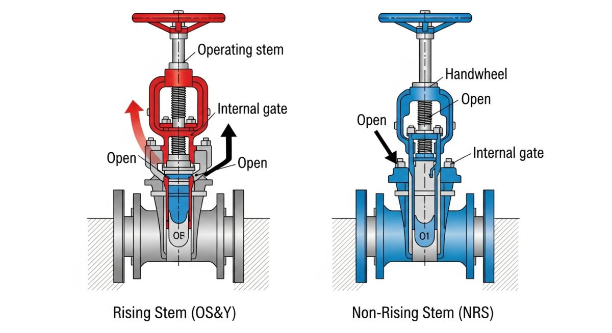
Figure 1: Comparison of Rising Stem (Left) vs. Non-Rising Stem (Right) mechanisms.
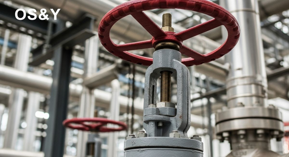
Type A Rising Stem (OS&Y)
OS&Y stands for Outside Screw and Yoke. In this design, the threads are machined on the upper part of the stem, located outside the valve body.
- ✔Thread Protection: Threads are not exposed to the process fluid, preventing corrosion and fouling.
- ✔Visual Indication: Operators can instantly tell if the valve is Open (stem is up) or Closed (stem is down) from a distance.
- ✔Lubrication: Threads are accessible for easy greasing.
- ❌Clearance: Requires significant vertical space to operate.
Type B Non-Rising Stem (NRS)
In an NRS valve, the stem rotates but does not move vertically. The threads are located at the bottom of the stem, inside the valve body, engaging with the gate.
- ✔Compact: Ideal for underground applications or tight spaces (e.g., ships, manholes).
- ❌Thread Corrosion: Threads are constantly wetted by the process fluid, leading to faster wear.
- ❌No Visual Check: You cannot see the valve position; you must rely on a separate position indicator.
| Feature | Rising Stem (OS&Y) | Non-Rising Stem (NRS) |
|---|---|---|
| Primary Use | Oil & Gas, Steam, Hazardous Fluids | Water Distribution, Underground, Ships |
| Lubrication | Easy (External fitting) | Difficult (Internal) |
| Failure Mode | Stem Bending | Thread Corrosion/Stripping |
3. Valve Stem Materials & Metallurgy (Critical for EPC)
Selecting the wrong stem material is the #1 cause of valve seizure. The stem must not only resist corrosion from the fluid but also possess high tensile strength to handle the actuator torque without twisting or snapping.
Standard Service: 13Cr (Type 410)
For general oil, gas, and steam applications, the industry standard is 410 Stainless Steel (commonly referred to as "13 Chrome").
- Why? It is martensitic, meaning it can be heat-treated to a high hardness. This hardness makes the threads durable and resistant to wear.
- Limitation: It has moderate corrosion resistance and is not suitable for sour service (H2S) unless NACE compliant.
Corrosive Service: 316 SS vs. 17-4PH
For corrosive fluids, 316 Stainless Steel is often requested. However, 316 is an austenitic steel (soft). Using a soft stem with a soft nut often leads to catastrophic thread galling. Therefore, high-strength alloys like 17-4PH or Duplex Stainless Steel (2205) are preferred for stems in corrosive environments.
Common API 600 Trim Material Chart (Stem Selection)
| Trim # | Stem Material | Typical Service |
|---|---|---|
| Trim 1 | 410 SS (13Cr) | Oil, Steam, General Purpose |
| Trim 5 | 410 SS (Hard Faced) | High Pressure Steam |
| Trim 8 | 410 SS (13Cr) | Universal Trim (Standard for EPC) |
| Trim 10 | 316 SS | Corrosive / Sea Water |
| Trim 12 | 316 SS | High Corrosive / Acid |
⚠️ The Engineering Rule of Hardness
To prevent thread galling (cold welding), the Valve Stem should have a hardness at least 50 Brinell Hardness Numbers (HB) higher than the Valve Disc or Yoke Nut. This ensures that if wear occurs, it happens on the cheaper, replaceable nut rather than the expensive stem.
4. Valve Stem Packing & Sealing
The space between the moving stem and the stationary valve bonnet is sealed using "Packing." In 2026, standard packing is no longer sufficient; Low-E (Low Emission) packing is mandatory for most petrochemical projects.
The Stuffing Box
This is the chamber where the packing rings (typically Graphite or PTFE) are inserted. A "Gland Follower" is tightened by bolts to compress the rings against the stem, creating a seal.
Stem Finish (Ra)
The stem surface must be extremely smooth (Ra < 0.8 µm) and perfectly straight. A rough stem acts like a file, shredding the packing material every time the valve is cycled, leading to leakage.
Low-E Standards (API 622 / 624)
To comply with EPA regulations and ISO 15848, modern valve stems must pass rigorous testing:
- API 622: Tests the packing material itself for leakage < 100 ppm.
- API 624: Tests the entire valve (stem + packing) over 310 mechanical cycles and thermal cycles to ensure leakage stays below 100 ppm.
EPCLand YouTube Channel
2,500+ Videos • Daily Updates
🦾 Valve Stem Thrust Load Calculator
Calculate the theoretical Axial Thrust force the valve stem must overcome to close against line pressure. This force dictates the required stem diameter and actuator torque.
*Calculation assumes full differential pressure across the seat area. Friction factors omitted for simplicity.
Effective Seat Area
Required Stem Thrust
Force needed just to resist pressure.
Bonus: Field Engineer's Maintenance Toolkit
Preventive maintenance is the key to extending valve life. Use this Stem Inspection Checklist during your next shutdown, and reference the glossary for component identification.
Safety Warning
Never attempt to loosen the gland bolts or remove a stem while the valve is under pressure. Always verify LOTO (Lock Out Tag Out) and depressurization before starting work.
1 Stem Inspection Protocol
2 Quick Glossary
If you hear a "squealing" noise when operating a gate valve, stop immediately. This is the sound of threads galling. Apply lubricant or risk total seizure.
6. Case Study: The "Seized Stem" Nightmare (Galling Failure)
The Challenge: Valve Stuck at 50% Travel
Context: During a scheduled turnaround on an offshore acid injection skid, operators attempted to close a 4-inch 316 Stainless Steel Gate Valve. The valve moved halfway and then locked solid. No amount of force on the handwheel could move it up or down.
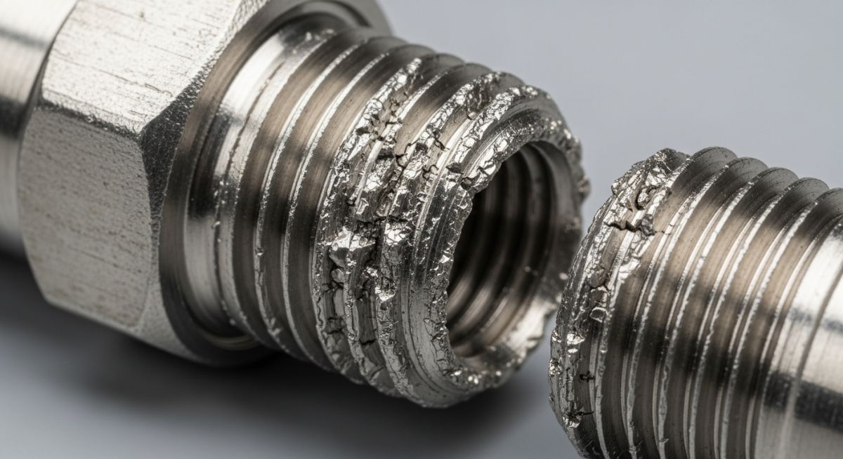
The Root Cause
Galling (Cold Welding): The valve manufacturer had supplied both the Stem and the Yoke Nut in the same grade of 316 Stainless Steel. When two similar metals with high friction coefficients slide against each other under load, they tear microscopic chunks of material, which instantly fuse together.
The Consequence
The valve was rendered inoperable. To fix it, the line had to be depressurized, and the valve bonnet was cut open. The stem threads were completely stripped and fused to the nut.
The Engineering Fix: Hardness Differential
The reliability engineer replaced the seized components with a revised material specification:
-
Component A
Stem (Remained 316 SS) Kept 316 for corrosion resistance against the acid.
-
Component B
Yoke Nut (Changed to Nitronic 60) Nitronic 60 is a high-strength alloy specifically designed to resist galling. Alternatively, Aluminum Bronze nuts are often used as a cheaper anti-galling solution.
Lesson Learned
Always ensure a hardness difference of at least 50 HB between the stem and the nut. Never specify "All 316SS Construction" without verifying the trim details for moving parts.
Frequently Asked Questions
What is "Backseating" a valve stem?
Can a bent valve stem be repaired?
How often should valve stems be lubricated?
Why do some stems have a "Smooth Finish" vs "Rough Finish"?
Final Thoughts on Valve Reliability
The valve stem is the only moving part that breaches the pressure boundary. Its failure isn't just a maintenance annoyance—it's a major safety hazard. Whether you select an OS&Y design for visibility or an NRS for compactness, prioritizing Material Hardness and Packing Quality is non-negotiable in 2026.
© 2026 Epcland Engineering. All Rights Reserved.
Content Verified by Atul Singla (Senior Piping Engineer).

Related posts:
![Cross-section diagram showing a steel solar pile foundation embedded in layered soil profiles for structural analysis.]()
Essential Geotechnical Pile Design Data for Utility-Scale Solar Structures
![Professional surveyor conducting Topographical Surveys for Solar Projects on a large-scale utility site with complex terrain.]()
Topographical Surveys for Solar Projects: A Technical Engineering Guide
![A geotechnical drill rig performing soil sampling on a large, open field intended for a utility-scale solar farm project.]()
Geotechnical Investigation for Solar Farms: Essential Site Design Guide
![Isometric site plan showing Utility Corridor Planning for Data Centres with color-coded power, water, and telecom infrastructure paths.]()
Utility Corridor Planning for Data Centres: A Strategic Engineering Guide
![Aerial view of a data centre site showcasing perimeter drainage systems, detention basins, and site grading for flood prevention.]()
Drainage Design Considerations for Data Centres: A Technical Guide
![Professional surveyor using a Total Station on a large data centre construction site for topographical mapping.]()
Topographical Surveys for Data Centre Projects: A Technical Guide