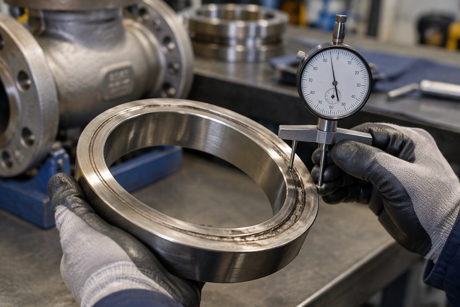
Valve Stem Corrosion Prevention and Industrial Repair Standards
In my two decades managing refinery turnaround piping systems, I have frequently witnessed plant technicians install fresh graphite packing rings onto deeply pitted valve stems, only to watch those exact seals fail within weeks. When a corroded and pitted industrial valve stem is pulled from its bonnet during a routine overhaul, its rough, oxidized surface acts like a micro-file against newly compressed packing rings. No matter how meticulously you torque the gland bolts or how expensive your expanded flexible graphite rings are, localized pitting depth exceeding manufacturing tolerances will invariably tear the braided matrix and lead to hazardous process leaks.
Addressing stem degradation requires a rigorous engineering workflow rather than a simple consumable swap. Surface anomalies, galvanic reactions between dissimilar trim alloys, and aggressive chemical attack demand systematic evaluation against established mechanical and metallurgical codes.
Key Engineering Takeaways
- Pitting depth on dynamic sealing diameters must be measured with calibrated depth micrometers before repacking decisions are finalized.
- Galvanic corrosion frequently occurs when austenitic stainless steel stems interact with carbon steel bonnets in saline service environments.
- Surface finishing requirements per ASME B18.2.1 dictate a maximum roughness average (Ra) of 16 micro-inches for optimal dynamic packing life.
Valve Stem Corrosion Mechanics and Metallurgy
When analyzing valve stem corrosion failures in high-pressure steam or hydrocarbon processing units, understanding the underlying electrochemical mechanisms is paramount. Stems manufactured from 304 or 316 stainless steel frequently experience localized crevice corrosion beneath stationary packing rings when stagnant moisture and chemical residues accumulate during operational idleness. This localized oxygen concentration cell creates acidic conditions, rapidly dissolving the protective chromium oxide passive film and forming deep, sharp-edged pits.
During actuation, these jagged pits cycle through the braided or die-formed packing rings. Each stroke shears microscopic fibers from the packing material, progressively destroying the labyrinth seal and creating leak paths for volatile organic compounds or high-temperature steam. To quantify this damage, maintenance engineers must apply strict dimensional verification formulas. The minimum allowable stem diameter (d_min) under combined tensile and torsional loading must be calculated using the following design equation:
Where M_b represents the bending moment induced by actuator side-loading, T_t represents the total torsional stem torque required to seat the wedge or ball, and S_allow is the allowable material stress limit defined in ASME B16.34 Table 1. If localized pitting depth exceeds 5% of the nominal stem diameter, stress concentration factors (K_t) escalate dramatically, requiring immediate stem replacement or engineered weld build-up and remachining.
Critical Safety Warning
Never attempt to polish out deep pits on safety-critical isolation valve stems using hand-held angle grinders or abrasive cloth. Removing excessive stock alters the stem-to-packing clearance, causing gland follower bottoming, loss of packing compression, and potential atmospheric blowouts of toxic or flammable process fluids.
In high-cycle control valve applications, stem side-load induced by pneumatic piston actuators accelerates galling and localized fretting corrosion. When combined with corrosive chemical washdowns or marine atmospheres, this mechanical wear strips away the passivated surface layer. Mitigating this requires upgrading to precipitation-hardening stainless steels such as UNS S17400 (17-4PH) heat-treated to H1150 condition, or applying high-velocity oxygen-fuel (HVOF) coatings of tungsten carbide or nickel-chromium-boron alloys.
Furthermore, thermal fatigue exacerbates corrosion kinetics in power plant feedwater systems operating above 350 degrees Celsius. Cyclic thermal expansion creates micro-fissures in oxide scales, allowing aggressive boiler water treatment chemicals—such as hydrazine and volatile amines—to penetrate the base metal grain boundaries. Inspection procedures must incorporate ultrasonic thickness testing and dye penetrant examination per ASME BPVC Section V to detect sub-surface intergranular stress corrosion cracking before catastrophic stem fracture occurs.
Advantages of Proactive Stem Restoration
- Extends the operational lifespan of expensive high-alloy valve trims without purchasing new assemblies.
- HVOF thermal spray coatings provide superior surface hardness (exceeding 60 HRC) and exceptional corrosion resistance.
- Precision cylindrical grinding restores exact OEM dimensional tolerances and micro-inch surface finishes.
- Reduces fugitive emissions by providing an ultra-smooth dynamic interface that preserves flexible graphite packing integrity.
- Significantly shorter lead times compared to forging and machining proprietary replacement valve stems from raw bar stock.
Disadvantages and Limitations
- Weld build-up processes introduce high thermal heat input, risking severe stem distortion and micro-structural degradation.
- Thermal spray coatings can suffer from interfacial delamination if substrate surface preparation and grit blasting are inadequate.
- Re-machined stems may exhibit altered mechanical properties if post-weld heat treatment (PWHT) parameters are not strictly controlled.
- Labor-intensive inspection and non-destructive testing requirements increase shop repair overhead costs.
- May void original equipment manufacturer (OEM) warranties unless certified repair procedures are executed by authorized service shops.
High-Pressure Steam Power Generation
Supercritical power plant turbine bypass and main steam isolation valves operate under extreme thermal cycling and high-velocity steam exposure. Preventing stem pitting through specialized cobalt-base alloy hardfacing ensures reliable emergency shutoff and prevents steam cutting across packing boxes.
Petroleum Refining and Hydroprocessing
Hydrocracker and catalytic reformer isolation valves handle sour gas and aggressive hydrocarbon streams containing hydrogen sulfide. Utilizing corrosion-resistant alloy overlay stems prevents localized sulfide stress cracking and ensures compliance with stringent EPA fugitive emission monitoring regulations.
Chemical and Petrochemical Processing
Chlor-alkali and acid transfer plants utilize specialized alloy stems such as Hastelloy C-276 and Titanium Grade 2. These materials resist aggressive chemical attack, eliminating pitting corrosion that would otherwise shred PTFE and graphite packing rings within hours of service.
Offshore Oil and Production Platforms
Subsea and topside production manifolds face severe marine atmospheric corrosion combined with produced sand erosion. Implementing super duplex stainless steel stems with ceramic thermal spray coatings protects against pitting and crevice corrosion in high-salinity offshore environments.
Valve Stem Corrosion Limits and Repair Specifications
Valve stem corrosion tolerances demand rigorous engineering evaluation to prevent catastrophic fugitive emissions and packing destruction. When inspecting industrial valve stems during a teardown, maintenance engineers must quantify pitting depth, surface roughness, and straightness against established codes such as ASME B16.34 and API 598. Pitting within the dynamic packing seal area cannot be tolerated, as micro-channels bypass newly installed graphite or PTFE rings immediately upon pressurization.
The following engineering reference table outlines critical rejection thresholds, acceptable surface finishes, and repair methodologies for common austenitic and martensitic stem alloys. Compliance with these parameters ensures that subsequent packing replacements achieve their intended design life without premature weeping or thermal binding in high-temperature hydrocarbon services.
| Stem Alloy / Material | Max Allowable Pitting Depth | Target Surface Finish (Ra) | Primary Restoration Method |
|---|---|---|---|
| ASTM A276 Type 410 | 0.000 in (Zero tolerance in seal zone) | 16 micro-inch (0.4 micro-meter) | Precision grinding and hard chrome plating |
| ASTM A276 Type 316 | 0.000 in (Zero tolerance in seal zone) | 16 micro-inch (0.4 micro-meter) | Laser cladding with Stellite 6 or equivalent |
| Almonel / Monel K-500 | 0.005 in max on non-sealing shank only | 32 micro-inch (0.8 micro-meter) | Selective brush plating or TIG weld overlay |
| Inconel 625 / UNS N06625 | 0.000 in (Zero tolerance in seal zone) | 16 micro-inch (0.4 micro-meter) | Submerged arc weld build-up and machining |
Note: Any pitting situated within the active stroke length of the packing box requires mandatory remediation prior to re-assembly, regardless of valve class or operating pressure rating.
Technical Mapping & Specifications Matrix
Industrial valve reliability depends on a complete understanding of material compatibility, environmental stress cracking, and mechanical sealing physics. When addressing chronic stem degradation, plant reliability engineers must map out physical parameters against recognized international standards to determine whether component replacement or specialized weld restoration is economically viable.
This entity matrix correlates critical engineering variables, governing industry standards, and structural acronyms associated with severe-service valve stems. Utilizing this structured mapping prevents miscommunication between maintenance shops and metallurgy laboratories during failure analysis investigations.
| Entity / Parameter | Standard Reference | Engineering Threshold |
|---|---|---|
| Fugitive Emissions Testing | ISO 15848-1 | Class AH / BH (< 50 ppm hydrocarbon leakage) |
| Surface Roughness Parameter | ASME B46.1 | Ra 16 micro-inches max along dynamic stroke |
| Valve Inspection & Testing | API 598 | Zero visible leakage during high-pressure shell test |
| Stem Straightness Tolerance | ASME B16.34 | Maximum total indicated runout (TIR) of 0.002 in |
Entity mapping confirms that surface preparation and dimensional alignment carry equal weight in eliminating fugitive emissions across high-pressure control valves.
Site Verification Checklist for Valve Stem Inspection
Field verification of corroded valve stems requires a systematic approach before any new packing ring installation is attempted. Skipping physical inspection steps or ignoring microscopic pitting inevitably leads to premature packing blowout, unplanned unit downtime, and severe environmental compliance violations.
Execute every verification checkpoint listed below during major turnaround valve overhauls. Cross-reference all physical measurements against plant maintenance specifications and applicable ASME B16.34 guidelines.
Mandatory Stem Overhaul and Inspection Protocol
- Thorough Solvent Cleaning: Strip all old graphite, PTFE, and grease residues from the stem surface using an approved industrial solvent and non-metallic brass wire brush.
- Visual & Tactile Pitting Check: Run a hardened steel scribe or fingernail across the polished length to detect invisible micro-pits that trap corrosive process media.
- Surface Profilometer Measurement: Verify that the dynamic sealing section meets the strict 16 micro-inch Ra finish mandated by engineering standards.
- Evenly measure stem diameter at three distinct axial points using outside micrometer calipers to confirm absence of necking or localized wear.
- Mount the stem on precision V-blocks and use a dial indicator to verify total indicated runout (TIR) remains within the 0.002 inch engineering limit.
- Inspect the stem threads and back-seat taper for galling, burrs, or chemical attack before applying certified anti-seize lubricant.
Validation Rule: If any single checkbox item fails inspection, the stem must be routed to the machine shop for restoration or discarded immediately. Never install new packing on a compromised substrate.
Field Case Study: Real-World Application
A critical high-pressure boiler feed water control valve at a 600 MW thermal power plant experienced catastrophic packing failure merely three weeks after a scheduled major overhaul turnaround. Despite installing premium flexible graphite packing rings with braided anti-extrusion wiper rings, severe leakage developed around the valve stem, forcing an unscheduled unit load reduction and an emergency isolation.
The Problem
Post-shutdown teardown revealed that maintenance technicians had replaced the worn packing rings without inspecting the underlying Type 410 stainless steel valve stem, which suffered from deep localized pitting caused by oxygen scavenging chemical attack.
- Deep corrosion pits slicing directly across the dynamic packing contact zone.
- Microscopic jagged edges acting like cutting blades against new flexible graphite material.
- Rapid mechanical degradation and shredding of packing rings during initial valve actuation cycles.
- Process water bypassing the primary seal barrier and leaking past the gland follower flange.
The Outcome
The engineering department overhauled the maintenance protocol by mandating rigorous stem inspections, machining tolerances, and surface finish verification prior to any packing box assembly.
- Replaced damaged valve stem with a new precipitation-hardened alloy resistant to boiler water pitting.
- Enforced strict profilometer checks guaranteeing a maximum 16 micro-inch Ra finish on all active stems.
- Achieved zero fugitive emissions through subsequent hydro-testing and two years of continuous high-load operation.
- Eliminated recurring emergency outages and saved over 150,000 in averted power generation losses.
Recommendation: Plant operators must never treat valve packing replacement as a simple consumable change-out. Always inspect the underlying metal stem for pitting, scoring, and chemical degradation to ensure long-term sealing integrity.
Frequently Asked Engineering Questions
Why does valve stem corrosion ruin newly installed packing rings?
- Surface pits act like micro-cutting tools against PTFE or graphite rings.
- Initial thermal cycling causes rapid abrasive wear across jagged rust edges.
- Gland adjustment cannot compensate for deep circumferential pitting defects.
- Fugitive emission limits under EPA Method 21 are routinely breached within days of startup.
What surface finish micro-inch limit is required after machining a stem?
- Stems must be checked with a calibrated profilometer across longitudinal and axial paths.
- Avoid circumferential tool marks that create spiral leak channels under pressure.
- Stellite hardfacing or laser cladding may be necessary if machining removes too much base metal.
- Compliance with MSS SP-120 guidelines guarantees consistent packing service life.
Can severe stem pitting be repaired via weld buildup and re-machining?
- Match weld filler metal chemistry precisely to the base metal to prevent galvanic corrosion.
- Perform post-weld heat treatment if mandated by base material specifications.
- Inspect for micro-cracking using liquid penetrant testing prior to final polishing.
- Ensure total radial runout remains under manufacturer-specified tolerances.
What causes rapid crevice corrosion underneath valve packing rings?
- Graphite packing contains cathodic carbon particles that accelerate anodic dissolution of adjacent base steel.
- Inhibitors in packing rings can leach out over time, leaving metal unprotected.
- Periodic stem exercising prevents localized stagnant fluid concentration cells.
- Selecting nickel-alloy or titanium stem materials prevents severe localized crevice attack.
How does stem straightening interact with pitted surface restoration?
- Perform cold straightening only within allowable elastic-plastic strain limits.
- Stress relieve components in a controlled furnace if severe bending occurred.
- Check final straightness on precision v-blocks with a dial indicator.
- Re-verify final dimensional tolerances against API 600 standards before installation.
Field Recommendation
When handling pitted and corroded valve stems during major overhauls, site engineers must enforce strict restoration protocols rather than executing quick-fix packing replacements that fail within weeks. Based on field observations across high-pressure refinery headers, I advise implementing the following decisive engineering actions:
- If stem pitting depth exceeds 10% of the nominal stem diameter or breaches the packing contact band, reject immediate polishing and mandate complete weld overlay or full stem replacement to prevent catastrophic blowout.
- When working in corrosive chemical services, always specify solid corrosion-resistant alloy stems such as Alloy 625 or Type 316 stainless steel with hard-faced packing contact regions rather than relying on thin protective plating that easily chips and flakes.
- Never install flexible graphite packing rings against a stem surface finished rougher than 16 micro-inches Ra; always require shop profilometer inspection sign-offs before releasing overhauled bonnet assemblies back to site construction crews.
- During routine preventative maintenance turnarounds, incorporate sacrificial corrosion inhibitors within the lantern rings of high-temperature valves to neutralize galvanic crevice attack between graphite packing sets and austenitic base metals.
Complete Course on
Piping Engineering
Check Now
Key Features
- 125+ Hours Content
- 500+ Recorded Lectures
- 20+ Years Exp.
- Lifetime Access
Coverage
- Codes & Standards
- Layouts & Design
- Material Eng.
- Stress Analysis
