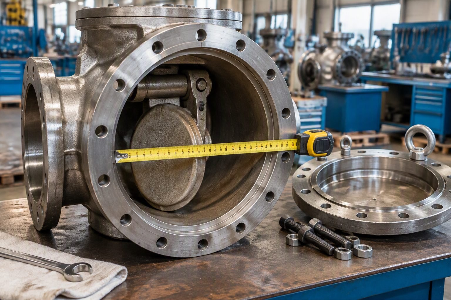
Valve Bonnet Flange Torque Sequence: Preventing Leaks and Preload Failure
In my two decades managing critical hydrocarbon units, I have witnessed countless fugitive emission incidents traced back to a single root cause: improper bolt-up during valve maintenance. When a technician tightens a valve bonnet flange sequentially around the perimeter rather than following a strict cross-pattern torque sequence, the resulting uneven gasket seating stress invariably causes localized crushing and delayed joint relaxation.
Valve bonnet flanges endure immense mechanical bending moments, thermal cycling, and line pressure thrusts. Mastering the controlled star-pattern valve bonnet flange torque sequence is not merely a routine mechanical task; it is an engineered science governed by strict fastener friction coefficients, lubricant torque scatter factors, and gasket yield limits.
Key Engineering Takeaways:
- Cross-pattern torque sequences eliminate localized gasket pinching.
- Multiple-pass tightening ensures consistent bolt scatter correction.
- Lubricant selection directly governs final achieved bolt preload.
Valve Bonnet Flange Torque Sequence Engineering Principles
When executing a maintenance overhaul on high-pressure gate, globe, or check valve bonnets, the flange connection acts as a complex spring-mass system. As each individual stud or bolt is tightened, it stretches elastically while compressing the gasket element and bending the bonnet and body flanges. Tightening bolt number two alters the clamping force of bolt number one due to elastic interaction. If technicians rely on a circular clock-face tightening method, the final bolts tightened will pull the flange cock-eyed, leaving the diametrically opposite side under-torqued.
To mitigate this, industry standards such as ASME PCC-1 mandate structured multi-pass cross-pattern sequences. For a standard 8-bolt or 16-bolt circular bonnet flange, the sequence follows an alternating diametric path: 1-5, 3-7, 2-6, 4-8. This pattern ensures that clamping loads are balanced across orthogonal axes, preserving parallelism between the bonnet and valve body seating faces.
Mathematical Formulation of Bolt Preload
Calculating the required target torque for a valve bonnet flange relies on the fundamental torque-tension relationship equation:
Where T represents the applied torque in foot-pounds or Newton-meters, K is the nut factor (dimensionless friction coefficient), d is the nominal bolt diameter, and F_p is the desired target bolt preload force. In my field experience, failing to account for the variability of the nut factor due to thread galling or anti-seize compound inconsistencies introduces a plus-minus thirty-five percent error in actual clamp load.
Critical Engineering Warning
Never exceed eighty percent of the bolt material yield strength during the final pass. Over-torquing bonnet studs leads to catastrophic plastic deformation, thread stripping, or bolt snap-off under thermal shock conditions in high-temperature steam services.
Multi-Pass Torque Tightening Protocol
Achieving the final target preload on a critical valve bonnet flange requires a strict four-pass protocol to allow gasket relaxation and elastic interaction settlement:
- Pass 1: Apply thirty percent of the final target torque using the specified cross-pattern sequence to seat the gasket evenly.
- Pass 2: Increase torque application to sixty percent following the identical cross-pattern sequence.
- Pass 3: Reach one hundred percent of target torque across the cross-pattern sequence.
- Pass 4: Perform a final rotational pass (clockwise or counter-clockwise adjacent check pass) at one hundred percent torque to verify that no adjacent bolts have relaxed.
Friction Coefficients and Lubrication Standards
The friction coefficient K dictates how much rotational energy translates into axial bolt stretch. Using dry threads results in high friction and low clamping force for a given torque reading. Conversely, applying heavy-metal anti-seize pastes drops the nut factor significantly, raising the risk of bolt yielding if standard tables are followed blindly.
Maintenance technicians must consult ASTM standards and manufacturer specification sheets to match the lubricant product with the exact bolt metallurgy, whether carbon steel B7 studs or high-alloy B8M stainless steel fasteners.
Advantages
- Eliminates localized flange pinching and uneven gasket crushing.
- Prevents fugitive emissions and catastrophic bonnet joint blowouts.
- Extends gasket lifespan under severe thermal cycling conditions.
- Ensures compliance with stringent environmental agency leak limits.
- Standardizes maintenance quality across turnarounds.
Disadvantages
- Demands significantly more labor time during emergency valve repairs.
- Requires precise calibration and maintenance of multiple torque tools.
- Prone to human error if technicians lose count of cross-pattern steps.
- Incompatible with cramped piping clearances without specialized extension sockets.
- Increased risk of thread galling during repetitive multi-pass tightening.
High-Pressure Hydrocracker Valve Bonnets
Refinery hydroprocessing units operate at pressures exceeding 200 bar and temperatures above 400 degrees Celsius. In these severe hydrogen service lines, valve bonnet flanges utilize heavy ring-joint gaskets where even minor preload skewing causes immediate metal-to-metal seating failure.
Strict adherence to a 4-pass star-pattern torque sequence ensures that the octagonal ring gasket deforms perfectly into the flange groove, preventing high-pressure hydrogen leaks and subsequent fires.
Nuclear Power Plant Main Steam Isolation Valves
Nuclear steam service lines experience extreme thermal shock during rapid startup and shutdown cycles. Main steam isolation valve bonnets are subjected to massive mechanical vibration and high-velocity steam flow.
Engineers apply hydraulic tensioners and controlled star-pattern torque sequences to maintain consistent bolt preload, eliminating thermal relaxation and avoiding radioactive steam containment breaches.
Cryogenic Liquefied Natural Gas (LNG) Piping
Cryogenic LNG valves operating at minus 162 degrees Celsius suffer from severe material contraction and bolt preload loss due to thermal shrinkage. Gaskets become brittle and lose elasticity.
Maintenance teams use low-temperature rated bolt lubricants combined with calibrated star-pattern torque sequences during ambient overhaul to guarantee leak-free operation once chilled down to operating temperature.
Acid Gas and Sour Water Stripper Units
Refinery sour gas systems handling hydrogen sulfide require corrosion-resistant alloy bolting (such as UNS N07718). These high-strength fasteners exhibit high sensitivity to torsional stress.
Using a meticulous cross-pattern torque protocol prevents localized over-stressing that triggers sulfide stress cracking in corrosive chemical process environments.
Valve Bonnet Flange Torque Specifications and Multi-Pass Requirements
Flange Bolting: Achieving uniform gasket stress on industrial valve bonnets requires strict adherence to multi-pass tightening protocols. In my professional piping commissioning experience, executing the correct bolt-up sequence under ASME PCC-1 guidelines prevents localized crushing and eliminates delayed bonnet joint leaks during high-temperature thermal cycling.
The following engineering data table outlines the standard multi-pass torque percentages, recommended pass increments, and practical site execution thresholds for high-integrity valve bonnet flange bolting operations across varying pressure classes.
| Tightening Pass | Target Torque Percentage | Required Tooling | Inspection Criteria |
|---|---|---|---|
| Pass 1 (Initial Snug) | 20% to 30% of Final Target | Hand Calibrated Torque Wrench | All nuts finger tight; uniform gap verified |
| Pass 2 (Intermediate) | 50% to 60% of Final Target | Calibrated Click-Type Wrench | Star-pattern sequence strictly maintained |
| Pass 3 (Final Target) | 100% of Calculated Target | Hydraulic or Pneumatic Torque Tool | Verify 100% bolt torque match across all studs |
| Pass 4 (Hot Pass / Re-torque) | 100% Final Target (Post-Thermal) | Calibrated Wrench at Operating Temp | Performed at stabilization per ASME B16.34 |
Proper tool calibration and strict sequencing eliminate uneven load distribution, safeguarding the gasket against localized relaxation and process media blowout.
Technical Mapping & Specifications Matrix
Entity Mapping: Industrial piping architecture relies on standardized interactions between fasteners, gaskets, valve bodies, and tightening hardware. Understanding these discrete engineering parameters ensures reliable mechanical containment under severe cyclic service conditions.
The following matrix establishes the core structural entities, governing standards, and material property parameters utilized during valve bonnet flange assembly validation.
| Engineering Entity | Governing Standard | Primary Function | Critical Parameter |
|---|---|---|---|
| Flange Bolting Assembly | ASME PCC-1 | Applies clamping force to maintain joint seal | Bolt preload accuracy within plus or minus 5 percent |
| Valve Bonnet Gasket | ASME B16.20 | Creates impermeable barrier across leak path | Minimum seating stress and creep relaxation limit |
| Stud Bolts and Nuts | ASTM A193 / A194 | High-tensile structural load transmission | Yield strength and thread lubrication coefficient |
| Valve Body Pressure Shell | ASME B16.34 | Contains internal process pressure safely | Wall thickness and flange face parallelism |
Maintaining strict alignment across these material and dimensional entities prevents catastrophic joint failure, ensuring compliance with international pressure equipment directives.
Site Verification Checklist: Valve Bonnet Flange Bolting Execution
Site Verification: Before energizing any high-pressure industrial piping loop, quality control inspectors must execute a rigorous pre-startup audit of all valve bonnet flange joints. In my field engineering practice, bypassing any single step in this verification checklist drastically increases the probability of fugitive emissions and thermal shock leaks.
Mandatory Field Inspection Protocol
- Flange Face Inspection: Verify that valve bonnet and body mating surfaces are free of pitting, radial score marks, scale, or residual gasket debris per ASME PCC-1 standards.
- Thread Lubrication Check: Confirm that high-temperature anti-seize compound is applied evenly to stud threads and nut bearing faces without contaminating gasket surfaces.
- Star-Pattern Mapping: Ensure field technicians clearly number or sequence all bonnet studs in accordance with the mandatory criss-cross star tightening sequence.
- Multi-Pass Verification: Validate that torque is applied in progressive increments (30%, 60%, 100%) using a calibrated torque wrench or hydraulic tensioner.
- Thread Protrusion Audit: Check that a minimum of two full thread pitches protrude past each tightened nut to confirm complete thread engagement.
- Hot Re-Torque Scheduling: Coordinate with operations to schedule a controlled hot re-torque pass once the piping system reaches operating temperature and pressure.
Completing this verification checklist ensures mechanical integrity, prevents gasket relaxation, and protects plant personnel from hazardous process fluid releases.
Field Case Study: Real-World Application
Case Study Overview: During a major refinery turnaround, recurring fugitive emissions were observed at a critical 12-inch high-pressure hydrotreater feed valve bonnet flange during initial hydrotesting. An emergency engineering investigation was commissioned to identify the root cause of the joint failure and implement corrective bolting procedures before unit startup.
Problem Analysis
Investigation revealed severe localized gasket crushing and uneven seating stress across the spiral-wound bonnet gasket due to improper installation practices.
- Maintenance contractors used a rotational circular tightening method instead of the mandatory star-pattern sequence.
- Torque was applied to 100 percent capacity in a single pass without intermediate staging increments.
- Stud thread friction coefficients varied wildly due to unapproved, non-lubricated thread conditions.
- Flange face parallelism exceeded allowable tolerance limits due to uneven initial bolt loading.
Corrective Outcome
Implementing strict ASME PCC-1 compliance protocols completely eliminated joint leakage and ensured long-term mechanical reliability.
- Replaced the damaged spiral-wound gasket with a fresh, certified ASME B16.20 metallic element.
- Enforced a four-pass star-pattern tightening sequence using calibrated hydraulic torque wrenches.
- Achieved uniform bolt preload verified by ultrasonic elongation measurements.
- Successfully passed subsequent hydrotesting at 1.5 times design pressure with zero leakage drops.
Recommendation for Plant Engineering: Always mandate certified mechanical bolting technicians and documented star-pattern torque sheets for all critical pressure boundary valve bonnet flanges.
Frequently Asked Engineering Questions
Why is a star-pattern torque sequence mandatory for valve bonnet flanges?
- Prevents localized crushing of spiral-wound or graphite gaskets.
- Maintains parallel alignment between bonnet flange and body flange faces.
- Distributes bolt load evenly across all fasteners to withstand hydro-test pressures.
How many torque passes are recommended during high-pressure valve bolting?
- Pass 1: Hand tight to 30 percent of target torque in star pattern.
- Pass 2: Increase torque value to 60 percent of final target.
- Pass 3: Apply 100 percent of calculated target torque across all studs.
- Pass 4: Perform a rotational pass at 100 percent to catch relaxed fasteners.
What role does anti-seize lubricant play in bolt preload calculations?
- Nut factor (K) must match the specific lubricant data sheet, typically ranging from 0.08 to 0.15.
- Dry threads require significantly higher torque values to achieve equivalent bolt stretch.
- High-temperature paste prevents stud seizure during future maintenance shutdowns.
When should hydraulic tensioning be preferred over torque wrenches?
- Recommended for studs exceeding 1.5 inches in diameter where manual torque is impractical.
- Eliminates torsional shear stress induced inside the stud body during tightening.
- Ensures precise control over residual bolt load and gasket stress limits.
How do thermal cycles affect bonnet flange bolt preload over time?
- Gasket material creep reduces initial seating stress after initial startup heat-up.
- Hot retorquing should be performed only when piping is depressurized and per safety guidelines.
- Selecting matching thermal expansion coefficients for studs and flanges minimizes load loss.
Field Recommendation
As a piping engineer overseeing critical hydrocarbon units, I advise field teams to enforce strict adherence to multi-pass tightening sequences and documented friction factors rather than relying on standard thumb rules. When commissioning high-pressure valve bonnets, make the following operational commitments:
- If working with high-alloy studs in sour service, always verify that the lubricant nut factor (K) is measured on-site using a bolt tension calibrator rather than trusting generic manufacturer catalogs.
- If bonnet flange leakage occurs during initial hydro-testing, never apply a simple single-bolt torque increase; instead, completely de-pressurize the line and re-execute the four-pass star pattern to restore flange parallelism.
- If flange sizes exceed 2 inches in stud diameter, mandate hydraulic tensioning over calibrated torque wrenches to eliminate torsional shear stresses and ensure repeatable fastener elongation.
- If the valve operates in cyclic thermal service above 400 degrees Fahrenheit, schedule a controlled hot-retorque pass during the first scheduled turnaround or stable shutdown window to counteract gasket creep and thermal relaxation.
Complete Course on
Piping Engineering
Check Now
Key Features
- 125+ Hours Content
- 500+ Recorded Lectures
- 20+ Years Exp.
- Lifetime Access
Coverage
- Codes & Standards
- Layouts & Design
- Material Eng.
- Stress Analysis
