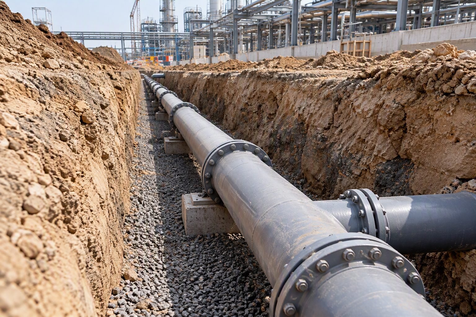
Underground Pipeline Slope Design and Civil Elevation Planning
In my two decades of managing major piping and civil engineering projects, I have frequently observed that the single most common failure point in underground gravity networks is an unverified trench elevation profile. When an underground industrial pipeline with visible flanged joints is installed in an open construction trench, civil elevation planning becomes the absolute baseline for determining whether the hydraulic gradient can sustain self-cleansing velocity. Without meticulous grade verification, low spots form, leading to sediment deposition, chemical pooling, and severe structural degradation over time.
Designing a reliable underground piping system demands a synchronized approach between structural soil mechanics, hydraulic flow calculations, and precise surveyor benchmarks. Every single flanged joint, change in elevation, and soil settlement parameter must be accounted for before trench backfilling begins. In this technical manual, I will break down the exact engineering methodologies required to master underground pipeline slope calculations, trench installation tolerances, and long-term elevation integrity.
Key Engineering Takeaways:
- Maintain absolute minimum gravity drainage slopes to guarantee self-cleansing solid transport velocities.
- Incorporate rigorous benchmark verification across all visible flanged joints during open trench construction.
- Align civil grading design with ASME B31.3 piping code restrictions and native soil bearing capacities.
Underground Pipeline Slope and Civil Elevation Calculations
When designing an industrial drainage network, the primary objective is to maintain a continuous, uninterrupted downward slope that prevents fluid stagnation. In my site design practice, I utilize the Manning equation as the fundamental mathematical model for sizing gravity flow conduits and establishing baseline invert elevations. The hydraulic gradient must offset friction losses while imparting enough kinetic energy to suspend heavy particulate matter suspended in industrial effluent.
The standard Manning formula for gravity flow velocity is expressed as V = (1.486 / n) * (R^(2/3)) * (S^(1/2)) in imperial units, where V represents mean velocity, n is the Manning roughness coefficient for the specific pipe material, R is the hydraulic radius, and S is the energy slope. For underground metallic and non-metallic piping networks designed under ASME B31.3, the internal roughness coefficient must account for potential scaling and chemical attack over the 30-year operational design life.
Core Hydraulic Design Parameters
- Minimum Self-Cleansing Velocity: Must achieve at least 0.75 m/s (2.5 ft/s) at half-pipe flow conditions to prevent silt accumulation.
- Standard Slope Gradients: Typically configured at 0.5% to 1.0% for nominal diameters under 300 mm, stepping down for larger utility headers.
- Invert Elevation Tolerances: Survey benchmarks must be maintained within a strict plus or minus 3 mm tolerance across every 10-meter bay.
- Flanged Joint Accessibility: Visible joints in open trenches require adequate clearance below the pipe invert to permit future torque verification.
Civil elevation planning begins with establishing absolute site benchmarks tied to national geodetic survey data. From these benchmarks, civil engineers map out the top-of-bank, trench subgrade, pipe bedding thickness, and pipe invert elevations. A common error I encounter during field audits is failing to account for cumulative soil consolidation beneath heavy metallic headers. If native subgrade soils are not compacted to at least 95 percent Modified Proctor density, differential settlement will alter the engineered pipeline slope.
When an underground industrial pipeline features visible flanged joints housed inside concrete or masonry inspection vaults, special structural considerations apply. Flanges cannot be buried directly in unexcavated soil due to corrosion risks and the inability to retorque bolts. The civil elevation plan must coordinate trench depth transitions precisely with vault floor elevations so that pipe stress transmitted through thermal expansion does not shear the stub ends or crack the concrete wall penetrations.
Critical Engineering Warning: Reverse Slopes and Sags
Allowing even a minor reverse slope (sag) in a gravity drainage line creates an immediate hydraulic dead zone. This traps corrosive process chemicals, accelerates localized pitting corrosion, and violates ASME B31.3 guidelines regarding fluid stagnation and structural integrity. Total station laser level checks must be performed continuously during open trench installation before any backfill material is introduced.
To execute precise elevation control, piping engineers work hand-in-hand with geotechnical specialists to evaluate trench side slope stability and groundwater table heights. Dewatering must be maintained continuously during pipe laying and joint makeup. If groundwater infiltrates an open trench and saturates the crushed stone bedding, buoyant forces can shift the pipeline upward, completely ruining an otherwise perfect gravity slope profile.
Ultimately, the success of underground drainage networks relies on a disciplined integration of civil surveying, hydraulic calculation, and strict adherence to code standards. By treating every flanged connection point as a rigid node requiring exact vertical alignment, engineering teams can eliminate costly rework and ensure decades of reliable, maintenance-free gravity drainage performance.
System Advantages
- Direct Visual Inspection: Open trench installation with accessible flanged joints permits immediate verification of bolt torque and leak checking.
- Simplified Maintenance: Vault-housed flanged connections allow straightforward disassembly for pipe cleaning, lining inspection, and gasket replacement.
- Precise Grade Control: Surveyors can directly measure invert elevations and laser-verify slope gradients before backfilling occurs.
- Adaptability: Easier to integrate lateral tie-ins and auxiliary drainage connections during the initial open construction phase.
- Code Compliance: Facilitates total compliance with ASME B31.3 inspection mandates for industrial process headers.
System Disadvantages
- High Excavation Costs: Maintaining open trenches over long industrial runs requires extensive shoring, dewatering, and safety management.
- Environmental Vulnerability: Open trenches expose piping and joints to rainwater ingress, debris contamination, and shifting soil conditions.
- Complex Vault Construction: Incorporating concrete access vaults around visible flanged joints significantly increases civil construction labor and material expenses.
- Settlement Risks: Differential soil settlement around heavy vaults can induce high bending moments on adjacent piping spools.
- Corrosion Exposure: Flanged metallic joints located in damp underground vaults demand specialized protective coatings and cathodic protection.
Petrochemical Effluent Drainage Networks
Refineries and chemical processing plants utilize underground gravity drainage headers to safely transport chemical waste and oily water. Integrating accessible flanged joints inside concrete interceptor vaults allows maintenance crews to conduct rapid leak checks and gasket replacements in accordance with strict environmental safety mandates.
Pharmaceutical Process Wastewater Piping
Clean-room facilities and active pharmaceutical ingredient manufacturing plants require impeccably sloped underground drainage lines to prevent stagnant pooling. Civil elevation planning ensures that high-purity stainless steel drainage mains maintain exact downward gradients without low points where bacterial growth could occur.
Power Generation Cooling Tower Blowdown
Thermal and nuclear power stations manage massive volumes of cooling water blowdown through large-diameter underground piping networks. Open trench installation with flanged expansion joints enables civil engineers to verify grade alignment and manage thermal growth across extensive facility plot plans.
Metallurgical Plant Acid Waste Drainage
Steel mills and metal finishing facilities rely on specialized acid-resistant piping systems installed in graded trenches. Civil elevation control ensures continuous gravity flow of corrosive pickling liquors to neutralization pits while protecting flanged connections from direct soil contact.
Food and Beverage Sanitary Sewer Mains
Large-scale food processing plants generate heavy organic wastewater requiring robust underground gravity mains. Precise slope verification and smooth invert transitions prevent solid accumulation, maintaining high hydraulic efficiency and satisfying municipal hygiene standards.
Underground Pipeline Slope and Elevation Design Parameters
Designing reliable gravity-fed drainage networks requires strict adherence to hydraulic gradients, minimum self-cleansing velocity constraints, and structural burial criteria. In my professional civil and piping engineering practice, I rely on standardized parameters to ensure that buried lines maintain self-cleansing velocities without causing excessive abrasive wear at pipe inverts or flange connections. The engineering data table below outlines the core parameters, typical design values, governing standards, and operational notes that dictate successful underground pipeline slope execution.
When evaluating pipe run elevations in open trenches, civil designers must balance hydraulic slope with maximum allowable burial depths dictated by ASME B31.3 Process Piping and ASCE manuals of practice. Failing to account for soil overburden pressure or differential settlement across flanged joints can lead to catastrophic joint leakage or localized pooling.
| Parameter Description | Standard Design Value | Governing Code / Standard | Operational Implication |
|---|---|---|---|
| Minimum Gravity Slope (4-inch Line) | 1.0% (10 mm/m or 1/8 inch/ft) | ASME B31.3 / WEF MOP FD-5 | Ensures minimum 0.6 m/s self-cleansing velocity to prevent suspended solid deposition. |
| Minimum Gravity Slope (8-inch Line) | 0.4% (4 mm/m or 1/2 inch/10ft) | ASME B31.3 | Larger hydraulic radius compensates for lower gradient while maintaining scour velocity. |
| Maximum Trench Excavation Depth | 6.0 Meters without Shoring Analysis | OSHA 1926 Subpart P | Requires engineered trench boxes, sloping, or sheet piling for worker safety and wall stability. |
| Bedding Compaction Density | 95% Modified Proctor Density | ASTM D2321 | Prevents differential pipe deflection and maintains uniform pipe invert slope over time. |
| Flanged Joint Clearance in Trench | Minimum 300 mm clearance around bolts | ASME B31.3 | Allows proper torque wrench access and future inspection of buried flange connections. |
Review these parameters thoroughly during the preliminary engineering phase to eliminate costly re-excavation work on site.
Technical Mapping & Specifications Matrix
Complex underground piping installations require a rigorous multidisciplinary approach, linking civil elevation surveying with mechanical piping design and geotechnical soil mechanics. The matrix below maps critical engineering entities, structural acronyms, physical parameters, and governing industry codes. In my industrial piping projects, utilizing this structured mapping guarantees that design assumptions made during civil grading translate accurately into safe mechanical execution in the field.
Cross-referencing these entities ensures complete traceability from initial laser-level site surveys to final hydrostatic testing and backfill sign-off under ASME B31.3 guidelines.
| Entity / Acronym | Full Technical Term | Primary Physical Parameter | Governing Standard / Ref |
|---|---|---|---|
| MSL | Mean Sea Level | Global vertical datum reference point | NAVD88 / NGS |
| invert | Pipe Invert Elevation | Lowest inside point of pipe cross-section | ASME B31.3 |
| HGL | Hydraulic Grade Line | Pressure head plus elevation head profile | ASCE Manual 60 |
| SWMM | Storm Water Management Model | Runoff hydrodynamics and pipe sizing | US EPA Standards |
| ASTM | American Society for Testing and Materials | Material specification and soil compaction | ASTM D2321 / F1673 |
Integration of these entities ensures complete alignment between civil site grading drawings and mechanical piping isometric documents.
Site Verification Checklist for Underground Pipeline Slope
Verifying underground pipeline slope and civil elevations prior to backfilling is one of the most critical quality control steps in industrial construction. Once a gravity drainage line is buried, rectifying slope errors requires expensive excavation and plant downtime. In my extensive site engineering career, I mandate the execution of a comprehensive verification checklist before any pipe bedding or backfill material is approved.
This checklist incorporates rigorous criteria from ASME B31.3 and ASTM D2321 to confirm that trench geometry, laser level accuracy, flanged joint alignment, and bedding compaction meet all engineering specifications without exception.
Mandatory Underground Pipeline Slope & Trench Inspection Steps
- Trench Bottom Grade Verification: Confirm that the excavated trench bed matches design invert elevations using a calibrated laser level at intervals not exceeding 3 meters.
- Minimum Slope Validation: Calculate actual fall over consecutive pipe runs to verify that the gradient meets or exceeds the specified minimum requirement per ASME B31.3.
- Bedding Material Compaction: Inspect granular bedding placement and verify achieving 95% Modified Proctor density per ASTM D2321 standards.
- Flanged Joint Alignment & Torque: Check that visible flanged joints in the open trench are properly aligned, gasketed, and torqued using calibrated bolt-tensioning equipment.
- Thrust and Anchor Block Placement: Ensure concrete thrust blocks and anchor supports are poured against undisturbed soil at all major directional changes and branch connections.
- Hydrostatic or Air Leak Testing: Complete preliminary pressure testing of the pipeline section while joints remain fully exposed in the trench prior to backfill approval.
Document all inspection sign-offs with signed surveyor logs and photographic evidence to maintain complete quality assurance records for the project dossier.
Field Case Study: Real-World Application
On a major chemical processing facility expansion project I managed recently, our civil team encountered a severe elevation discrepancy during the installation of a 300-meter underground gravity drainage line containing multiple flanged spool pieces. The open trench inspection revealed that localized soil settling and inaccurate laser-level calibration had caused a reverse slope condition over a 24-meter stretch, threatening to stall effluent flow and violate ASME B31.3 gravity drainage criteria.
Field Problem Identified:
An uncorrected elevation sag and improper trench bed compaction created a 15 mm counter-slope in a critical flanged process drainage line.
- Laser level surveyor error during initial trench excavation and grading.
- Excessive bending moment induced across the exposed flanged joints due to uneven pipe support.
- Risk of solids accumulation and corrosive chemical pooling upstream of the low point.
- Potential non-compliance audit finding during final environmental and mechanical turnover inspections.
Left unaddressed, this localized slope inversion would have led to premature pipeline blockage, severe localized corrosion at the flanged connections, and expensive emergency excavation after plant commissioning.
Engineering Outcome & Resolution:
Immediate civil re-grading and installation of engineered supports restored full gravity drainage compliance across the entire pipeline run.
- Re-compacted the pipe bedding using crushed stone aggregate to achieve 95% Modified Proctor density per ASTM D2321.
- Installed adjustable mechanical pipe chairs to relieve stress on flanged joints and prevent future differential settlement.
- Passed secondary hydrostatic pressure and flow testing with zero joint leakage recorded.
This case study demonstrates why rigorous in-trench elevation verification and strict adherence to civil engineering standards are non-negotiable for successful underground piping design.
Frequently Asked Engineering Questions
What is the absolute minimum slope required for gravity drainage underground pipelines?
The minimum gravity slope depends strictly on pipe diameter and self-cleansing velocity requirements, adhering to industrial civil standards.
- For standard 4-inch sewer lines, a slope of 1.0 percent (1/8 inch per foot) is commonly specified.
- For larger 6-inch to 8-inch drainage runs, the slope can often be safely reduced to 0.5 percent while maintaining a 2.0 feet per second scouring velocity.
- Engineers must always verify that invert levels account for absolute maximum expected solid loading per ASME B31.3 guidelines.
Why are flanged joints generally discouraged on underground buried pipelines?
Buried flanged connections introduce severe mechanical and corrosion risks that complicate long-term civil maintenance integrity.
- Flanges create localized stress concentration points during soil settlement and backfill compaction cycles.
- Bolting hardware is highly susceptible to accelerated galvanic corrosion and crevice attack underground.
- Welded joints or specialized restrained mechanical joints should always be prioritized for subterranean runs.
How do civil engineers establish accurate elevation bench-marks in open trenches?
Establishing reliable elevation controls requires a combination of optical leveling instruments and strict grade rod positioning.
- Set temporary bench marks (TBMs) outside the zone of excavation to prevent shifting during earthmoving activities.
- Use laser levels combined with magnetic grade rods for continuous trench bottom verification.
- Cross-check invert elevations every 10 meters against the master civil site drawing layout.
What impact does soil compaction have on underground gravity slope alignment?
Inadequate bedding compaction leads to differential pipe settlement, resulting in belly formation and drainage failure.
When managing complex underground civil elevation projects involving gravity drainage runs, I strongly advise practicing engineers to execute the following field judgments:
- If your geotechnical report indicates high groundwater tables or unstable native soils, choose crushed angular stone bedding over native excavated material because it prevents differential settling and stabilizes the engineered slope against hydraulic shifting.
- If visible flanged joints are mandated in a buried environment due to equipment tie-in constraints, choose a concrete valve vault or dedicated manhole housing instead of direct backfilling because it ensures ongoing access for bolt torque verification and prevents premature gasket corrosion.
- If site space restrictions force close proximity to heavy surface traffic zones, choose a thicker pipe wall schedule or reinforced concrete encasement because standard pipe stiffness ratings will fail under concentrated dynamic wheel loads over time.
- If minor elevation miscalculations threaten minimum gravity drainage velocities near discharge points, choose an intermediate cleanout or drop connection rather than forcing an abrupt slope transition because it preserves hydraulic efficiency and simplifies future maintenance pigging operations.
Complete Course on
Piping Engineering
Check Now
Key Features
- 125+ Hours Content
- 500+ Recorded Lectures
- 20+ Years Exp.
- Lifetime Access
Coverage
- Codes & Standards
- Layouts & Design
- Material Eng.
- Stress Analysis
