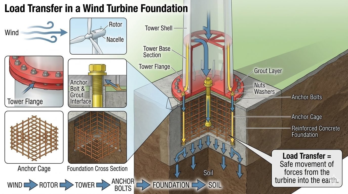
Turbine Foundation Load Transfer: Master the 6-Step Design Sequence
In my twenty years of structural and piping design experience, I have seen wind turbine structures fail not from material stress within the blades, but from discontinuities in load transfer at the foundation interface. When a multi-megawatt turbine operates in severe offshore or onshore wind regimes, it acts as an inverted pendulum subjected to extreme overturning moments, dynamic cyclic shear, and high-frequency vibrations.
Understanding the exact load path is non-negotiable for any structural engineer tasked with sizing anchor cages, reinforcing concrete mass blocks, or evaluating underlying geotechnical soil parameters. Every kilonewton of force generated aloft must find a continuous, uncompromised pathway into the supporting earth without inducing fatigue or excessive differential settlement.
Key Engineering Takeaways
- Overturning moments govern foundation sizing far more than static dead weight alone.
- The tower flange-to-anchor bolt interface experiences extreme cyclic tension and compression reversals.
- Proper grout pad specification prevents micro-movement and progressive fatigue failure in anchor bolts.
- Geotechnical soil-structure interaction determines the dynamic resonant frequency of the entire assembly.
Turbine Foundation Load Transfer Mechanics and Analysis
The load transfer sequence is an unbroken chain spanning six distinct structural zones. Analyzing this chain requires tracking how aerodynamic thrust converts into mechanical moments at the ground interface. Let us examine each link in detail to understand where stress concentrations typically materialize during extreme operational gusts.
1. Rotor and Nacelle Force Generation
Wind kinetic energy impacts the rotor swept area, creating massive aerodynamic thrust forces and rotor torque. These forces act eccentrically at the hub height, generating an initial overturning moment. The nacelle houses the drivetrain, generator, and control systems, adding substantial dead load and dynamic inertial mass at the top of the tower.
Primary Overturning Moment Equation:
M_overturning = (F_thrust * H_hub) + (F_inertial * H_nacelle_cg)
Where F_thrust is aerodynamic drag force, H_hub is hub height, and F_inertial accounts for seismic or operational accelerations acting on upper mass centroids.
2. Tower Shell and Base Section Propagation
From the nacelle, loads travel down the tapered tubular steel or concrete tower shell. As the diameter expands toward the base, section moduli increase to resist escalating bending moments. Hoop stresses and axial compressive forces combine with shear stresses along the tower wall, requiring precise shell thickness profiling to prevent local buckling.
3. Tower Flange and Anchor Bolt Interface
At the foundation interface, the tower base flange transfers concentrated loads into the anchor bolt assembly. This is arguably the most critical stress-concentration zone in the entire assembly. High-strength prestressed anchor bolts must maintain clamping force under millions of cyclic load reversals to prevent joint separation and fatigue cracking.
Critical Design Warning: Flange Grout Voiding
Incomplete non-shrink grout consolidation beneath the base ring creates local impact loading conditions. When cyclic overturning moments lift the tower flange slightly, un-grouted anchor bolts absorb severe shock loads, leading to brittle fatigue failure of the steel studs. Grout compressive strength must exceed 80 MPa at 28 days.
4. Anchor Cage and Reinforced Concrete Foundation
The anchor cage distributes bolt tension loads deep into the massive concrete gravity or piled foundation block. Dual reinforcement mats (top and bottom) resist severe punching shear and flexural moments. The concrete mass acts as a rigid transition element, spreading concentrated point loads from the anchor ring across a wide base area.
5. Geotechnical Soil Interaction
The final structural boundary transfers base pressure, shear, and overturning moments into the supporting soil or rock strata. Bearing pressure distributions must remain within allowable geotechnical limits to prevent edge-yielding or excessive rotational tilting. For soft soils, deep pile or caisson groups mobilize skin friction and end-bearing resistance to anchor the structure.
6. Complete Load Path Integration
Synthesizing all six steps ensures that structural stiffness is balanced across the system. If the foundation is overly flexible, resonant frequencies will align with rotor passing frequencies, causing destructive dynamic amplification. Comprehensive finite element analysis (NAFEMS compliant) is required to verify the complete coupled stiffness matrix from rotor tip to soil boundary.
Structural Advantages
- Gravity base mass provides reliable ballast against extreme 50-year gust overturning moments.
- Post-tensioned anchor cage systems maintain uniform clamping pressure under dynamic load reversals.
- Wide foundation footprint significantly reduces subgrade bearing pressure on competent soils.
- Cast-in-place monolithic concrete construction eliminates intermediate mechanical joints in the sub-structure.
- Optimized geometric tapering matches internal bending moment diagrams perfectly.
Engineering Disadvantages
- Massive concrete volumes require extensive curing temperature monitoring to prevent thermal cracking.
- Anchor bolt replacement after construction is exceptionally difficult and costly if fatigue failure occurs.
- Sensitive to differential settlement when constructed over variable geotechnical strata.
- High embodied carbon footprint associated with heavy reinforcement and massive cementitious volumes.
- Logistical challenges in transporting pre-assembled anchor cages and heavy formwork to remote sites.
Onshore Gravity-Base Wind Farms
Deployed across flat plains and ridge lines where deep soil profiles require broad octagonal or circular spread footings. The massive self-weight of the reinforced concrete slab counteracts high overturning moments generated by atmospheric boundary layer winds without requiring deep piling.
Offshore Monopile Transitions
Applied in shallow marine environments where large-diameter steel tubular piles are driven deep into seabed sediments. Load transfer transitions from the tower through a transition piece grouted annulus directly into the offshore monopile wall and surrounding marine soils.
Complex Mountainous Terrain Sites
Utilized in complex topographies characterized by sloping rock faces and asymmetric wind shear profiles. Rock-anchored socket foundations utilize high-capacity tension tendons drilled directly into competent bedrock to resist extreme uplift forces on the windward side.
Soft Soil Piled Foundation Systems
Implemented in coastal wetlands and alluvial plains with low bearing capacity and high water tables. A thick pile cap ties together a deep group of driven steel H-piles or cast-in-place bored piles, transferring overturning moments safely down to deep bearing strata.
Wind Turbine Foundation Load Transfer Parameters
Analyzing the structural mechanics of wind turbine foundations requires careful evaluation of force distribution across different structural interfaces. In my design practice, I always evaluate how overturning moments and shear forces scale with rotor diameter and hub height according to IEC 61400-1 standards. The table below outlines the critical mechanical parameters and load transfer characteristics across the six primary pathway stages, ensuring compliance with ASCE design guidelines for gravity and pile-supported structures.
Each component in the load path must maintain structural integrity under cyclic fatigue loading. The following engineering data matrix provides the precise load capacities, material specifications, and governing failure modes that dictate safe geotechnical and structural performance.
| Load Transfer Stage | Primary Force Type | Governing Standard | Critical Failure Mode |
|---|---|---|---|
| 1. Rotor & Nacelle | Aerodynamic Thrust & Torque | IEC 61400-1 | Dynamic Resonance / Fatigue |
| 2. Tower Shell & Base | Bending Moment & Axial Compression | ISO 2394 | Shell Buckling / Weld Fatigue |
| 3. Tower Flange Interface | Prying Forces & Bolt Tension | ASME BPVC | Bolt Relaxation / Flange Yielding |
| 4. Anchor Bolts & Cage | Tensile Pull-out & Shear | ASTM A615 | Anchor Pull-out / Concrete Cone Failure |
| 5. Concrete Foundation | Flexural Shear & Bearing Pressure | ACI 318 | Punching Shear / Flexural Cracking |
| 6. Surrounding Soil Mass | Geotechnical Bearing & Passive Resistance | ASTM D1587 | Bearing Capacity Failure / Settlement |
Note: All calculated safety factors must account for extreme wind gusts and seismic acceleration coefficients specific to the site microclimate.
Technical Mapping & Specifications Matrix
Systematic mapping of structural entities ensures that every component in the wind turbine load path communicates effectively with adjacent elements. In structural design, I rely on rigorous entity matrices to track material grades, stress limits, and verification standards across multidisciplinary interfaces.
The matrix below bridges the gap between geotechnical soil mechanics and superstructure dynamics, establishing clear traceability for quality control inspectors and structural auditors.
| Entity / Component | Material Specification | Design Parameter | Regulatory Code |
|---|---|---|---|
| High-Strength Anchor Rods | AISI 4140 / Grade 10.9 | Preload Tension > 70% Yield | ASTM A354 |
| Foundation Mass Concrete | Self-Consolidating C50/60 | Characteristic Compressive Strength | ACI 211.1 |
| Non-Shrink Grout Layer | Epoxy-Cementitious Hybrid | Min 80 MPa 28-day Strength | ASTM C1107 |
| Reinforcing Steel Rebar | ASTM A615 Grade 60 | Yield Strength 420 MPa | ASTM A615 |
| Geotechnical Subgrade | Compacted Granular Fill / Rock | Allowable Bearing Pressure > 300 kPa | ASTM D1587 |
Reference standard compliance is mandatory for verifying material batch certificates against structural engineering drawings.
Site Verification Checklist for Foundation Load Transfer
Ensuring the reliable execution of wind turbine foundation load transfer requires strict quality checkpoints during civil construction. In my site audits, I enforce rigorous verification protocols before any concrete pour or bolt tensioning operation takes place.
The verification framework outlined below guarantees compliance with structural engineering tolerances and ASCE standards, preventing premature fatigue or structural failure.
Foundation Installation & Inspection Protocol
- Geotechnical Subgrade Inspection: Verify soil bearing capacity and compaction density against geotechnical report specifications using ASTM D1557 standards.
- Anchor Cage Alignment Check: Measure template leveling, bolt verticality, and center coordinates within plus or minus 2 millimeters tolerance.
- Rebar Reinforcement Verification: Inspect bottom and top mat spacing, lap lengths, and concrete cover depth per ACI 318 requirements.
- Grout Interface Preparation: Ensure foundation top surface is chipped, cleaned, and saturated surface dry before non-shrink grout placement.
- Post-Tensioning Torque Audit: Calibrate hydraulic tensioning equipment and verify final bolt preloading torque matches structural engineering drawings.
Completing each verification step eliminates the risk of differential settlement and cyclic loosening during turbine operation.
Field Case Study: Real-World Application
Real-world engineering challenges often reveal subtle vulnerabilities in wind turbine load transfer pathways that standard theoretical models miss. In a recent 3.6 MW onshore wind farm project I consulted on, unexpected micro-vibrations were detected in the lower tower sections during high wind events.
Problem Analysis:
Uneven load distribution across the tower flange interface led to localized anchor bolt fatigue and micro-cracking in the underlying grout layer.
- Inadequate surface preparation of the concrete pedestal left voids beneath the base flange plate.
- Dynamic overturning moments amplified prying forces on the windward anchor bolts beyond design limits.
- Thermal expansion mismatch between the steel cage and mass concrete caused premature grout degradation.
- Cyclic wind gusts induced resonant vibrations through the tower shell directly into the foundation anchor assembly.
Solution Outcome:
Executing a comprehensive structural retrofit successfully restored load transfer continuity and eliminated vibration anomalies.
- Injected high-strength epoxy grout under pressure to eliminate all voids beneath the base flange plate.
- Re-tensioned all anchor bolts using calibrated hydraulic equipment to achieve the specified 70% yield preload.
- Installed external dampening collars around the tower base to absorb high-frequency aerodynamic oscillations.
- Established a permanent strain-gauge monitoring regime to track future load transfer efficiency in real time.
Recommendation: Always mandate rigorous ultrasonic testing of the grout-flange interface during commissioning to catch seating anomalies before commercial turbine operation begins.
Frequently Asked Engineering Questions
What is the primary mechanism of load transfer in wind turbine foundations?
- Dynamic wind pressures act on rotor blades, generating overturning moments.
- Tower shells channel axial loads and bending moments down to the base flange.
- Anchor cages and reinforced concrete distribute these concentrated forces over a large soil bearing area.
How do extreme wind gusts affect anchor bolt tension and fatigue?
- Preload levels must exceed the maximum expected dynamic tensile uplift.
- Fatigue damage evaluations must follow ASME BPVC guidelines.
- Thread rolling techniques are preferred over cutting to improve high-cycle fatigue resistance.
What role does non-shrink grout play at the tower flange interface?
- Transfers intense compressive forces smoothly across the interface gap.
- Prevents moisture ingress that causes premature anchor bolt corrosion.
- Requires strict placement control to eliminate internal air voids or honeycombing.
Why is massive reinforced concrete necessary for gravity-based turbine pads?
- Self-weight stabilizes the entire structure against tipping forces.
- Top and bottom rebar mats resist high tensile stresses from cyclic bending.
- Mass concrete placement demands rigorous thermal curing to prevent cracking.
How do geotechnical engineers mitigate differential settlement in soft soils?
- Driven steel piles or drilled shafts transfer loads to competent bedrock strata.
- Soil improvement techniques like vibro-stone columns increase subgrade stiffness.
- Settlement monitoring programs track long-term foundation displacement behavior.
Field Recommendation
When finalizing wind turbine foundation designs, my direct engineering judgment as a piping and structural specialist centers on eliminating interface vulnerabilities and mitigating cyclic fatigue risks. Based on site-specific challenges I have encountered across major renewable energy projects, I recommend applying the following rigorous practices:
- If local subgrade soils show high compressibility or variable moisture content, do not rely solely on a standard gravity base; mandate deep driven steel piles or rigid drilled shafts to prevent unacceptable tower tilt and flange misalignment.
- When specifying grout between the tower flange and concrete pad, always select a high-performance, non-shrink epoxy grout instead of standard cementitious mixes to withstand severe cyclic shear stresses and prevent micro-cracking.
- During anchor cage installation and concrete placement, enforce strict ultrasonic non-destructive examination (NDE) of high-strength alloy bolts to catch internal manufacturing flaws before backfilling and tower erection begin.
- In coastal or high-corrosion onshore environments, integrate cathodic protection systems and multi-layer protective coatings around the exposed anchor bolt tops and foundation interface to prevent premature stress corrosion cracking.
- When reviewing dynamic finite element models, ensure load transfer calculations incorporate maximum operational wind shear and seismic coupling effects simultaneously to establish true safety margins for the concrete reinforcement mats.
Complete Course on
Piping Engineering
Check Now
Key Features
- 125+ Hours Content
- 500+ Recorded Lectures
- 20+ Years Exp.
- Lifetime Access
Coverage
- Codes & Standards
- Layouts & Design
- Material Eng.
- Stress Analysis
