Table of Contents
Applying Maximum Shear Stress Theory Tresca Theory of Failure
In my 20 years of piping engineering, I have seen many young engineers rely blindly on software outputs without understanding the underlying physics. When designing high-pressure piping systems or pressure vessels, selecting the right failure theory is the difference between a safe plant and a catastrophic rupture. The Tresca criterion, also known as the Maximum Shear Stress Theory, has been my reliable companion for conservative ductile material design. It simplifies complex multi-axial stress states into a straightforward comparison against standard tensile test data, ensuring that our designs remain safely within the elastic limit.
Key Engineering Takeaways
- Highly conservative yield prediction for ductile metals under multi-axial loading.
- Simpler mathematical formulation compared to the Von Mises distortion energy theory.
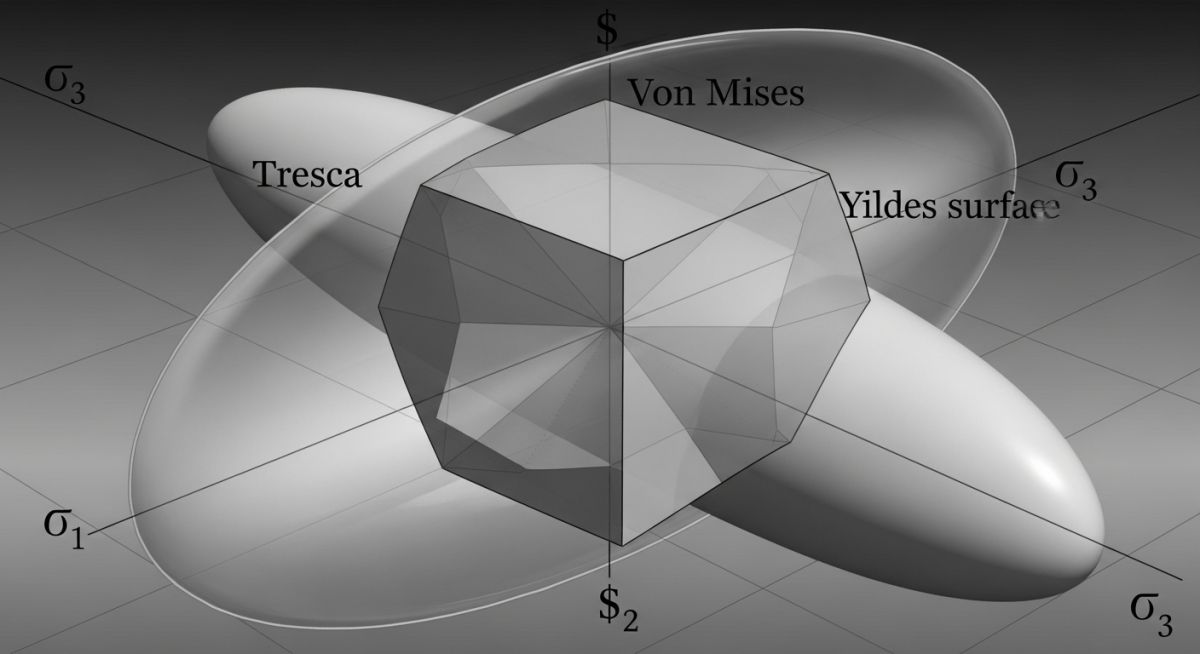
- Hexagonal yield surface nested entirely inside the Von Mises ellipse, representing a safer design margin.
- Mandated by specific sections of the ASME Boiler and Pressure Vessel Code for stress intensity limits.
- Particularly effective for pure shear, torsion-heavy, and thick-walled cylinder applications.
Complete Course on
Piping Engineering
Check Now
Key Features
- 125+ Hours Content
- 500+ Recorded Lectures
- 20+ Years Exp.
- Lifetime Access
Coverage
- Codes & Standards
- Layouts & Design
- Material Eng.
- Stress Analysis
Understanding the Tresca Theory of Failure Mechanics
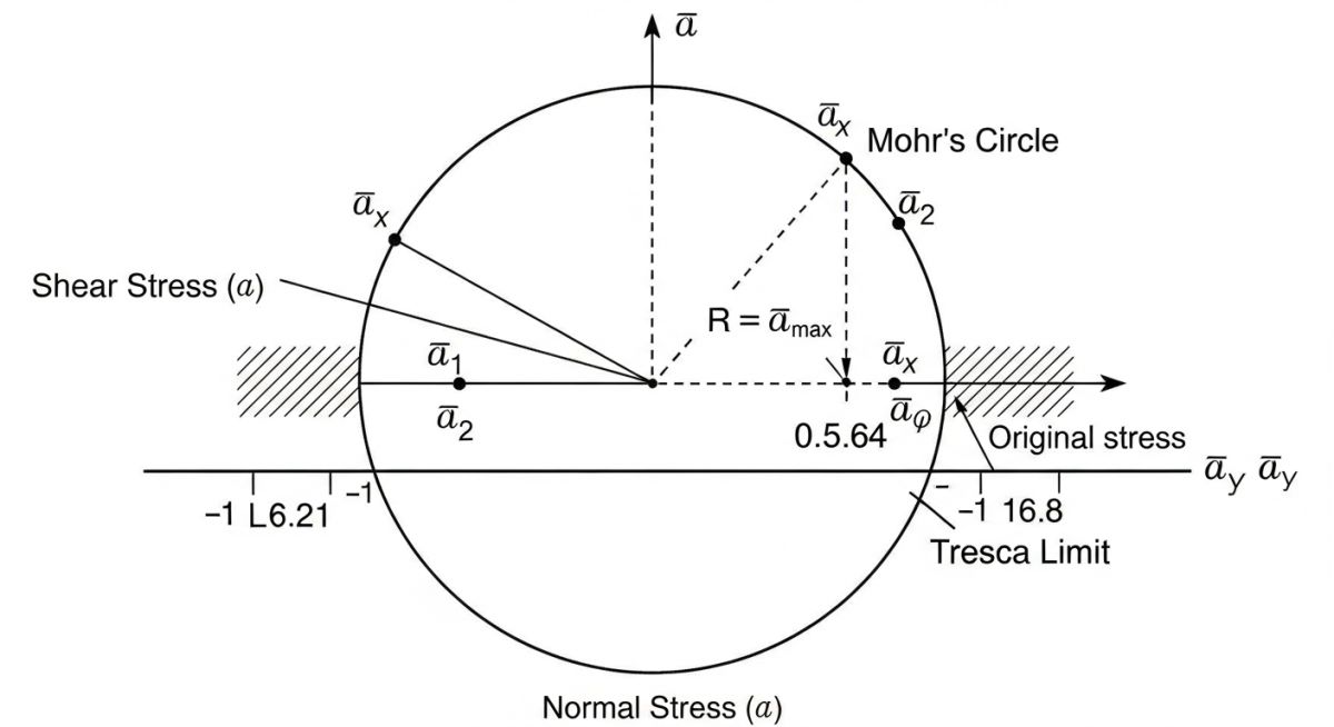
Maximum Shear Stress Criterion: The mathematical representation where the absolute maximum shear stress, calculated as half the difference between the maximum and minimum principal stresses, is limited to half of the material yield strength. This ensures that multi-axial stress states do not exceed the elastic limit of ductile materials.
To apply this theory in daily engineering work, we must first determine the principal stresses acting on a point: sigma_1, sigma_2, and sigma_3. By convention, we order these stresses such that sigma_1 is the largest and sigma_3 is the smallest. The maximum shear stress (tau_max) is defined by the following plain text formula:
In a simple uniaxial tension test, yielding occurs when the tensile stress reaches the yield strength (S_y). At this exact moment, the maximum shear stress in the test specimen is:
According to the Tresca criterion, yielding in a multi-axial stress state begins when tau_max equals tau_yield. Therefore, the yield condition is simplified to:
This difference (sigma_1 – sigma_3) is often referred to as the “stress intensity” in pressure vessel design codes like ASME Section VIII Division 2. If we introduce a factor of safety (N), the design equation becomes:
Field Warning: Material Ductility Limits
Never apply the Tresca criterion to brittle materials such as cast iron or high-carbon steels with less than 5 percent elongation. Brittle materials do not fail by shear slip along slip planes; they fail due to maximum tensile separation. Applying this theory to brittle components will lead to unsafe designs and sudden, catastrophic structural failures.
When we plot this relationship in a two-dimensional stress space (where sigma_3 is zero), the Tresca yield locus forms an unequal hexagon. This hexagon is completely inscribed within the Von Mises yield ellipse. Because the Tresca boundary lies inside the Von Mises boundary, it always predicts yielding at equal or lower stress levels. In pure shear conditions, the Tresca theory is approximately 15.5 percent more conservative than the Von Mises theory. This built-in safety margin is why I prefer it for critical piping manifolds handling hazardous fluids.
The table below outlines common ductile piping and structural materials, their minimum yield strengths, and the corresponding allowable shear stress limits calculated using the Tresca criterion with a standard safety factor of 1.5.
| Material Specification | Yield Strength S_y (MPa) | Tresca Yield Limit (MPa) | Allowable Shear Stress (N = 1.5) | Typical Application |
|---|---|---|---|---|
| ASTM A106 Grade B | 240 | 120 | 80 | Standard process piping |
| ASTM A312 TP316L | 170 | 85 | 56.7 | Corrosive chemical lines |
| ASTM A105 Carbon Steel | 250 | 125 | 83.3 | Forged flanges and fittings |
| ASTM A350 LF2 | 240 | 120 | 80 | Low-temperature service |
This matrix maps the core technical entities, physical parameters, and code references required to execute a compliant stress analysis using the maximum shear stress theory.
| Entity / Parameter | Symbol | Plain Text Formula | ASME / API Reference | Design Impact |
|---|---|---|---|---|
| Stress Intensity | S_int | sigma_1 – sigma_3 | ASME Sec VIII Div 2 | Controls plastic collapse limits |
| Max Shear Stress | tau_max | (sigma_1 – sigma_3) / 2 | API 6A / ISO 10423 | Determines localized slip initiation |
| Allowable Stress | S_all | S_y / N | ASME B31.3 Chapter II | Establishes safe operating envelope |
Verifying Designs with the Tresca Theory of Failure
Design Verification Protocol: A systematic engineering review process to confirm that calculated principal stresses are correctly ordered and that the maximum shear stress remains below the allowable limits. This protocol ensures compliance with industrial piping and pressure vessel standards.
Before signing off on any high-pressure piping or structural design, I insist that my team runs through this verification checklist. This ensures that we have not missed any critical load combinations or misapplied the material limits.
Site Verification Checkpoints
-
[ ]
Identify all primary, secondary, and peak stresses from finite element analysis (FEA) or analytical hand calculations. -
[ ]
Calculate and sort the principal stresses such that sigma_1 is greater than or equal to sigma_2, which is greater than or equal to sigma_3. -
[ ]
Compute the maximum shear stress using the absolute difference between the maximum and minimum principal stresses. -
[ ]
Verify that the material is ductile, possessing an elongation of at least 5 percent before applying this theory. -
[ ]
Apply the appropriate factor of safety as mandated by ASME B31.3 or ASME Section VIII. -
[ ]
Compare the Tresca yield limit with the Von Mises stress to quantify the conservatism margin for the client. -
[ ]
Document the calculations in the formal engineering design record for third-party audit and compliance verification.
Field Case Study: Real-World Application
Case Problem: Underestimated Torsional Yielding
A high-pressure hydraulic manifold manufactured from ASTM A105 carbon steel was experiencing micro-cracking along the weld neck junctions. The original design team used the Von Mises criterion, which predicted a safety factor of 1.15. However, cyclic pressure fluctuations and high torsional loads from misaligned piping actuators caused localized yielding that the distortion energy theory underestimated due to its less conservative yield envelope.
Case Outcome: Redesign and Resolution
I stepped in and re-evaluated the manifold using the Tresca Theory of Failure. By calculating the absolute maximum shear stress, we discovered that the actual safety factor was only 0.98 under peak torsional loads. We redesigned the manifold wall thickness using the Tresca limits, increasing the thickness by 12 percent. This modification completely eliminated the yielding and micro-cracking, ensuring trouble-free operation for over five years.
My direct recommendation is to always use the Tresca criterion when your piping system is subjected to high torsional loads combined with internal pressure. The extra margin of safety is worth the minor increase in material weight, especially when dealing with hazardous or high-pressure fluids.
Frequently Asked Engineering Questions
What is the primary difference between the Tresca and Von Mises failure theories?
Why is the Tresca theory considered conservative for ductile materials?
Can I use the Tresca theory of failure for brittle materials?
How does ASME Section VIII utilize the Tresca criterion?
What is stress intensity in the context of the Tresca theory?
When should I choose Von Mises over Tresca in piping design?
===

Related posts:
![A mechanical sucker rod pumpjack operating in an oil field at sunset]()
What is Sucker Rod Pump System in Oil Production?
![Piping material engineer reviewing technical specifications on a tablet in an industrial plant.]()
How a Piping Material Engineer Drives Industrial Project Success
![Industrial refinery plant showing various types of static equipment]()
What is Static Equipment? Types and List of Static Equipments
![Side-by-side comparison of industrial process piping and power plant steam piping systems.]()
Differences Between ASME B31.3 and B31.1: B31.3 vs B31.1
![Large industrial steel storage tank under construction with cranes and scaffolding]()
Storage Tank Construction Method Statement: Step-by-Step Engineering Guide
![Cutaway diagram of a globe control valve highlighting the internal valve trim components]()
What is a Valve Trim? Types, Components, and Selection


